GS752TP, GS728TP, GS728TPP Gigabit Smart Switches
Trademarks
GS752TP, GS728TP, and GS728TPP Gigabit Smart Switches
Support
Revision History
Contents
Configuring Switching Information
Configure Quality of Service
Monitoring the System
Appendix a Hardware Specifications and Default Values
Getting Started
Getting Started with the Netgear Switch
Switch Management Interface
Connect the Switch to the Network
Discover a Switch in a Network with a Dhcp Server
GS752TP, GS728TP, and GS728TPP Gigabit Smart Switches
Switch Discovery in a Network Without a Dhcp Server
To assign a static IP address
Configure the Network Settings on the Administrative System
Password
To configure a static address on the switch
To log on to the web interface
Access the Management Interface from the Web
Understand the User Interface
Navigation Tabs, Configuration Menus, and Screen Menu
Device View
Configuration and Status Options
Command Buttons
Link Submenu Links
Power/Status LED
Following image shows the device view of the Netgear switch
User-Defined Fields
Help Screen Access
Use Snmp
GS752TP, GS728TP, and GS728TPP Gigabit Smart Switches
Naming Convention for Switch Interfaces
Interface Naming Convention
Configuring System Information
To define system information
Management
System Information
IP Configuration
System status information
GS752TP, GS728TP, and GS728TPP Gigabit Smart Switches
IPv6 Network Configuration
VLANs
To configure the global settings for an IPv6 Interface
IPv6 Network Neighbors
To view the IPv6 Network Interface Neighbors
Time Configuration
Time
To configure the time through Sntp
Sntp Server Configuration
Sntp Global Status fields
To remove an Sntp server
To configure a new Sntp server
To change the settings for an existing Sntp server
DNS Configuration
To configure the global DNS settings
Host Configuration
To add a static entry to the local DNS table
Green Ethernet Configuration
Dynamic Host Configuration table fields
To configure the Green Ethernet Configuration features
Green Ethernet Interface Configuration
To configure the Green Ethernet Detail feature
Green Ethernet Detail
Green Ethernet Summary
PoE
System PoE Advanced PoE Configuration
PoE Configuration
To configure PoE trap settings
PoE Configuration Field Descriptions
PoE Port Configuration
To assign a timer to the port
Timer Global Configuration
Timer Schedule
To create a timer
To configure timer settings
Community Configuration
Snmp
To add a new Snmp community
To add a host that receives Snmp traps
Trap Configuration
To configure Snmp trap settings
To modify information about an existing Snmp recipient
To configure the trap flags
Trap Flags
Snmp v3 User Configuration
Snmp Supported MIBs
To configure SNMPv3 settings for the user account
Lldp
System Lldp Advanced Lldp Configuration
Lldp Configuration
To configure global Lldp settings
Lldp Port Settings
To configure Lldp port settings
Network Policy Number. The policy number
LLDP-MED Network Policy
To view LLPD-MED information
LLDP-MED Port Settings
To configure LLDP-MED settings for a port
Local Information
To display the Lldp Local Device Information screen
Detailed local information
Field Description Managed Address
MED Details
Lldp neighbors information
Neighbors Information
To display the Lldp Neighbors Information screen
Port Details
Field Description Port Details
Managed Addresses
Lldp Unknown TLVs
Services-DHCP Snooping
Dhcp Snooping Global Configuration
Dhcp Snooping Interface Configuration
GS752TP, GS728TP, and GS728TPP Gigabit Smart Switches
Dhcp Snooping Binding Configuration
To configure Dhcp binding settings
Dhcp Snooping Persistent Configuration
To configure Dhcp snooping persistent settings
Configuring Switching Information
Ports
Global Configuration
To configure global configuration settings
Port Configuration
To configure port settings
GS752TP, GS728TP, and GS728TPP Gigabit Smart Switches
LAG Configuration
Link Aggregation Groups
To configure LAG settings
LAG Membership
To create a LAG
Lacp Configuration
To configure Lacp
Lacp Port Configuration
To configure Lacp port priority settings
Vlan Configuration
VLANs
To configure VLANs
Vlan Membership Configuration
To configure Vlan membership
Port Vlan ID Configuration
To configure Pvid information
Voice Vlan
Voice Vlan Properties
GS752TP, GS728TP, and GS728TPP Gigabit Smart Switches
Voice Vlan OUI
Voice Vlan Port Setting
To configure Voice Vlan port settings
00036B. CISCO1
00D01E. Pintel
To configure OUI settings
CISCO2 000FE2. H3C
00E0BB COM 00040D. AVAYA1 001B4F. AVAYA2
Auto-VoIP Configuration
To enable Auto-VoIP
Spanning Tree Protocol
STP Configuration
To configure STP settings on the switch
STP Status information
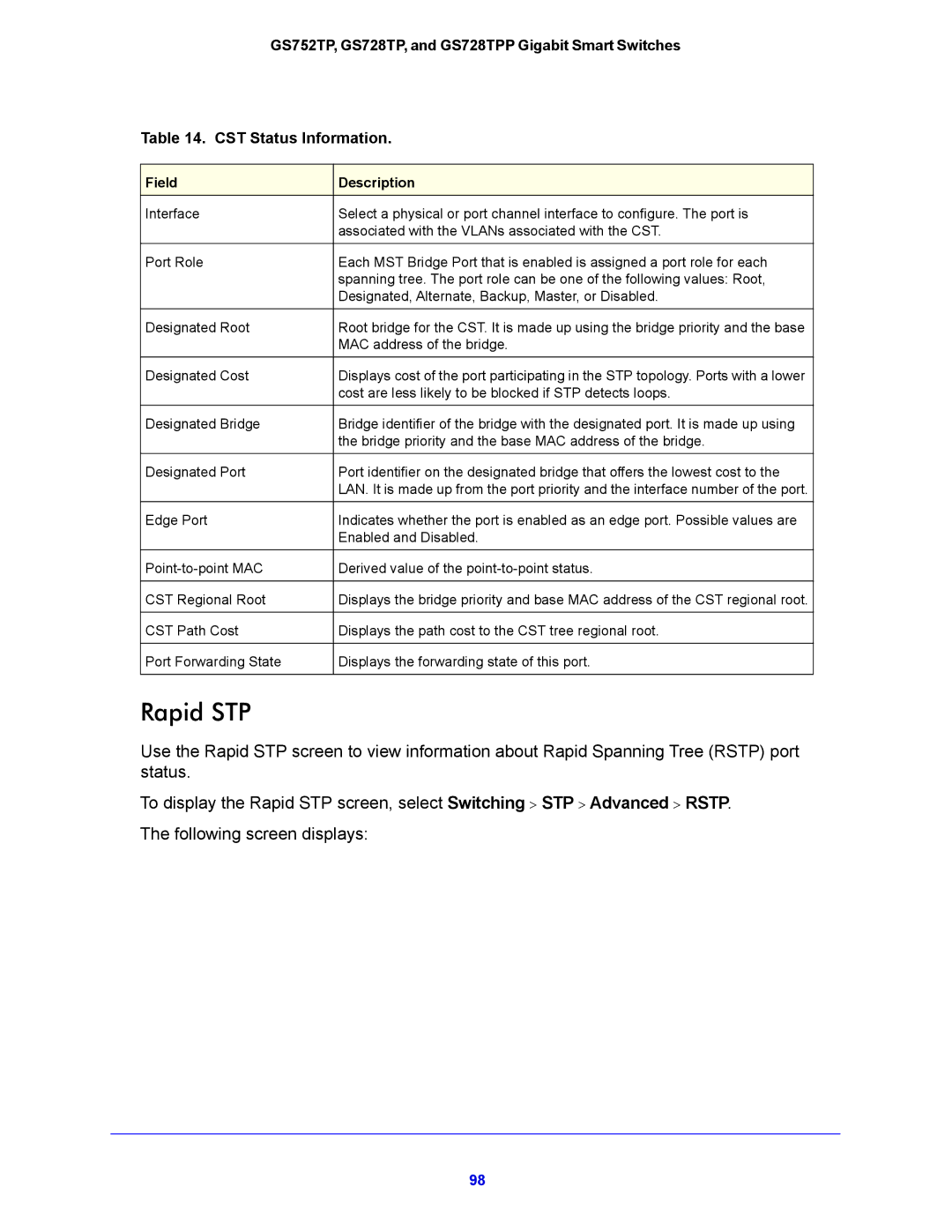
CST Configuration
To configure CST settings
Mstp Status Information
CST Port Configuration
To configure CST port settings
CST Port Status
Rapid STP
MST Configuration
Rstp Status Information
To modify an MST instance
MST Instance Information
MST Port Configuration
To configure MST port settings
MST port configuration information
Value for Port Path Cost is
Multicast
Mfdb Table
To view the Mfdb Table screen
Auto-Video Configuration
Mfdb Statistics
To configure Auto-Video
Igmp Snooping
Igmp Snooping Configuration
To configure Igmp Snooping
Igmp Snooping Table
Igmp Snooping Status
Igmp Snooping Table
Igmp Snooping Vlan Configuration
To configure Igmp snooping settings for VLANs
Igmp Snooping Querier
Igmp Snooping Querier Configuration
To configure Igmp Snooping Querier settings
Igmp Snooping Querier Vlan Configuration
To configure Querier Vlan settings
Igmp Snooping Querier Vlan Status
114
MLD Snooping Configuration
MLD Snooping
To configure MLD snooping
MLD Vlan Configuration
To configure the MLD Vlan
Multicast Router Vlan Configuration
To configure the Multicast Router Vlan
Multicast Group Configuration
Static Multicast Address
Multicast Group Membership
To configure the Multicast Forward All feature
Multicast Forward All
Forwarding Database
Address Table
To search for an entry in the MAC Address Table
MAC Address Table Fields
Dynamic Address Configuration
To configure the Dynamic Address setting
Configuring Routing
Configure IP Settings
To access the IP Configuration screen
Configure Vlan Routing
Vlan Routing Wizard
To configure Vlan settings
Configure Vlan Routing
To configure Vlan routing settings
Configure and View Routes
To configure routes
Learned Routes Table Fields
Subnet Mask
Configure ARP
ARP Cache
ARP Entry Configuration
To add a static entry to the ARP table
Global ARP Configuration
To configure the global ARP settings
ARP Entry Management
To remove entries from the ARP table
Configure Quality of Service
Class of Service
Basic CoS Configuration
To configure global CoS settings
CoS Interface Configuration
To configure CoS settings for an interface
Queue Configuration
To configure CoS queue settings
802.1p to Queue Mapping
To map 802.1p priorities to queues
Dscp to Queue Mapping
To map Dscp values to queues
Differentiated Services
Defining DiffServ
Diffserv Configuration
Dscp Violate Action Mapping
To configure the Dscp violate action mapping
Class Configuration
To add a new class
To configure a class
IPv6 Class Configuration
Service Type
To configure an IPv6 class
To configure the class match criteria
Policy Configuration
To configure a DiffServ policy
To configure the policy attributes
154
To configure DiffServ policy settings on an interface
Service Configuration
Service Statistics
156
Managing Device Security
To change the login password for the management interface
Management Security Settings
Change Password
To reset the password for the management interface
Configure Radius Settings
Global Configuration
To configure global Radius server settings
Radius Server Configuration
Accounting Server Configuration
To configure the Radius accounting server
To configure global TACACS+ settings
Configure TACACS+
TACACS+ Configuration
TACACS+ Server Configuration
Authentication List Configuration
Http Authentication List
Https Authentication List
168
Configure Management Access
Http Configuration
Secure Http Configuration
To configure Https settings
Certificate Management
To manage certificates
Click Generate Request
Access Control
To generate a certificate request
Access Profile Configuration
To set up a security access profile
To configure a security access rule
Access Rule Configuration
To add a security access rule
Port Authentication
802.1x Configuration
To configure global 802.1x settings
Configuration
Port Authentication
178
179
Port Summary
Port Summary Fields
181
Traffic Control
Storm Control
To configure storm control settings
Port Security Interface Configuration
To configure port security settings
Security MAC Address
To convert learned MAC addresses
To configure protected ports
Protected Ports
Configure Access Control Lists
ACL Wizard
To create an ACL
ACL fields according to selected ACL type
ACL Based on Fields
MAC ACL
To configure a MAC ACL
MAC Rules
To configure MAC ACL rules
MAC Binding Configuration
To configure MAC ACL interface bindings
MAC Binding Table
MAC Binding Table fields
To configure an IP ACL
IP ACL
IP Rules
IP Extended Rules
199
200
IPv6 ACL
To add an IPv6 ACL
IPv6 Rules
To add an IPv6 rule
203
IP Binding Configuration
205
IP Binding Table
IP Binding table fields
Monitoring the System
Switch Statistics
To display switch statistics
209
Port Statistics
Port Detailed Statistics
212
213
214
EAP Statistics
To display a EAP Statistic
Cable Test
To display cable information
Cable Status
Logs
Buffered Logs
To configure the Buffered Logs settings
Server Log
To add a remote log server
221
Trap Logs
To view Snmp traps
To configure port mirroring
Mirroring
224
System Resources Utilization
To view Tcam utilization
Maintenance
To reboot the switch
Reset
Device Reboot
Factory Default
To reset the switch to the factory default settings
Upload File Types
Upload a File from the Switch
Tftp File Upload
To upload a file from the switch to the Tftp server
Http File Upload
Download File Types
Download a File to the Switch
Tftp File Download
To download a file to the switch from a Tftp server
To download a file to the switch from by using Http
Http File Download
Dual Image Configuration
File Management
To configure Dual Image settings
Dual Image Status
237
Ping
Troubleshooting
To configure the settings and ping a host on the network
Ping IPv6
Traceroute
241
Remote Diagnostics
To configure the remote diagnostics feature
Help
To connect to online support
Online Help
Support
To access the user guide
User Guide
Registration
To register the switch
Hardware Specifications and Default Values
249
Switch Features and Defaults
Feature Sets Supported Default
251
252
Configuration Examples
Virtual Local Area Networks VLANs
Sample Vlan Configuration
Match Every. False CoS
Access Control Lists ACLs
Sample MAC ACL Configuration
Vlan ID
Sample Standard IP ACL Configuration
Destination MAC Mask Ffff
Match Every. True
Rule ID Action. Deny Match Every. False Source IP Address
Rule ID
Differentiated Services DiffServ
Class
Traffic Conditioning Policy
DiffServ Traffic Classes
Create Policies
Sample DiffServ Configuration
Class Name. Class1 Class Type. All
Policy Selector. Policy1 Member Class. Class1
Protocol Type. UDP Source IP Address
Destination IP Address Destination Mask
Assign Queue Policy Attribute. Simple Policy
802.1x
Sample 802.1x Configuration
Secret Configured. Yes
Mstp
Sample Mstp Configuration
Switch 1 Switch 2 Switch 3
MST ID
MST ID Priority Vlan ID
To configure a switch to perform inter-VLAN routing
Configure Vlan Routing with Static Route
Sample Vlan Routing Configuration
Vlan Routing Overview
271
Europe EU Declaration of Conformity
Netgear Wired Products
Regulatory Compliance Information
FCC Requirements for Operation in the United States
FCC Declaration Of Conformity
FCC Radio Frequency Interference Warnings & Instructions
Index
275
276
277