DATASHEET
PM5349 S/UNI-QUAD
ISSUE 6 | SATURN USER NETWORK INTERFACE | |
|
|
|
NOTES:
1.OENB is the active low output enable for D[7:0].
2.RDATENB is the active low output enable for RSOC, RDAT[15:0], and RXPRTY[1:0].
3.When set high, INTB will be set to high impedance.
4.HIZ is the active low output enable for all OUT_CELL types except D[7:0], RXPRTY[1:0], RDAT[15:0], and INTB
5.A[7] is the first bit of the boundary scan chain.
12.3.1Boundary Scan Cells
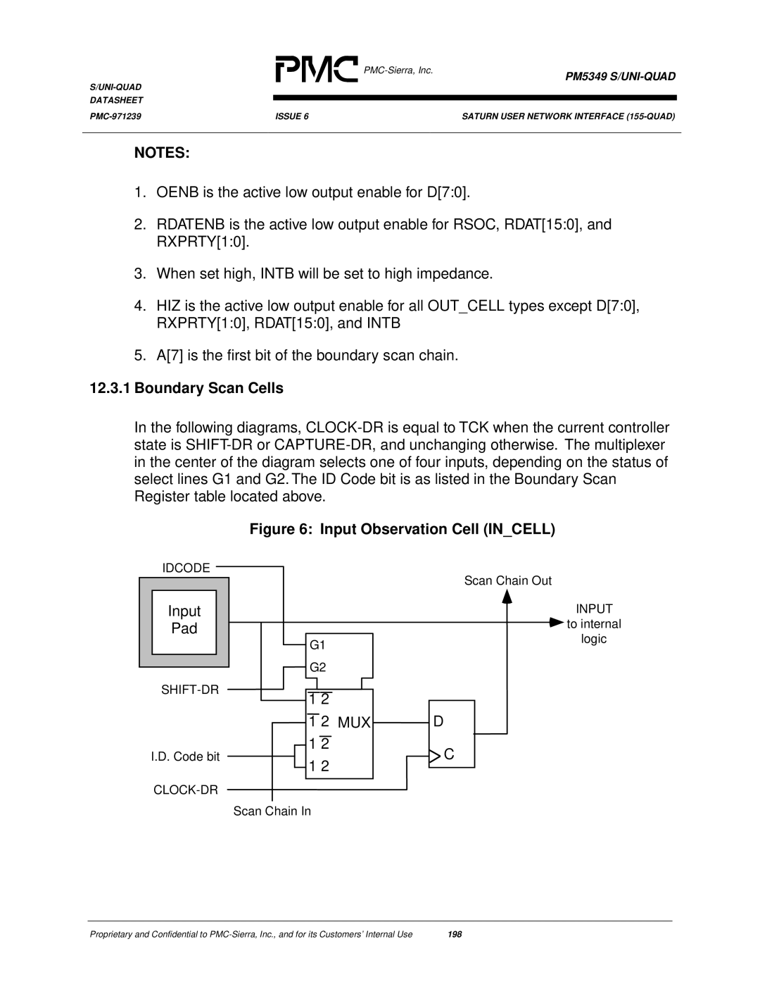
In the following diagrams,
Figure 6: Input Observation Cell (IN_CELL)
IDCODE
Input
Pad
I.D. Code bit
G1
G2
1 2
1 2 MUX
1 2
1 2
Scan Chain In
Scan Chain Out
INPUT
 to internal
logic
D
![]() C
C
Proprietary and Confidential to | 198 |