|
| PM5349 |
| |
|
|
| ||
|
|
|
| |
DATASHEET |
|
|
|
|
|
|
|
| |
|
|
|
| |
ISSUE 6 |
| SATURN USER NETWORK INTERFACE |
| |
|
|
|
|
|
Pin Name | Type | Pin | Function |
|
| No. |
|
|
|
|
|
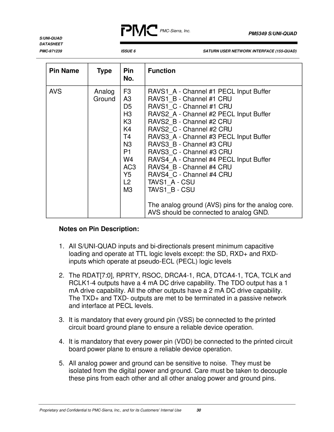
AVS | Analog | F3 | RAVS1_A - Channel #1 PECL Input Buffer |
| Ground | A3 | RAVS1_B - Channel #1 CRU |
|
| D5 | RAVS1_C - Channel #1 CRU |
|
| H3 | RAVS2_A - Channel #2 PECL Input Buffer |
|
| K3 | RAVS2_B - Channel #2 CRU |
|
| K4 | RAVS2_C - Channel #2 CRU |
|
| T4 | RAVS3_A - Channel #3 PECL Input Buffer |
|
| N3 | RAVS3_B - Channel #3 CRU |
|
| P1 | RAVS3_C - Channel #3 CRU |
|
| W4 | RAVS4_A - Channel #4 PECL Input Buffer |
|
| AC3 | RAVS4_B - Channel #4 CRU |
|
| Y5 | RAVS4_C - Channel #4 CRU |
|
| L2 | TAVS1_A - CSU |
|
| M3 | TAVS1_B - CSU |
|
|
| The analog ground (AVS) pins for the analog core. |
|
|
| AVS should be connected to analog GND. |
|
|
|
|
Notes on Pin Description: |
| ||
1.All
2.The RDAT[7:0], RPRTY, RSOC,
The TXD+ and TXD- outputs are met to be terminated in a passive network and interface at PECL levels.
3.It is mandatory that every ground pin (VSS) be connected to the printed circuit board ground plane to ensure a reliable device operation.
4.It is mandatory that every power pin (VDD) be connected to the printed circuit board power plane to ensure a reliable device operation.
5.All analog power and ground can be sensitive to noise. They must be isolated from the digital power and ground. Care must be taken to decouple these pins from each other and all other analog power and ground pins.
Proprietary and Confidential to | 30 |
