DATASHEET
PM5349 S/UNI-QUAD
ISSUE 6 | SATURN USER NETWORK INTERFACE | |
|
|
|
H4:The multiframe indicator byte is a payload specific byte, and is not used for ATM payloads.
13.2 ATM Cell Data Structure
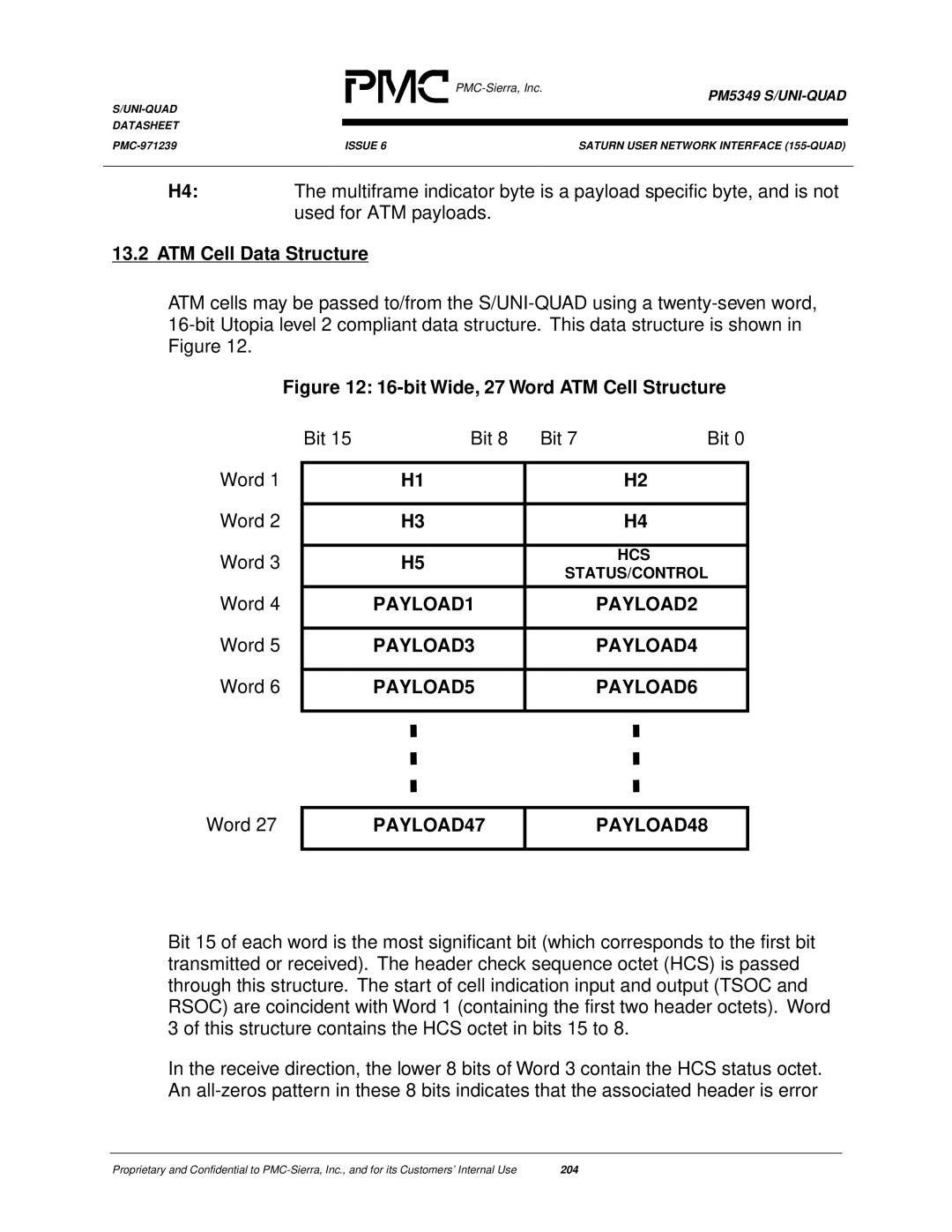
ATM cells may be passed to/from the
Figure 12: 16-bit Wide, 27 Word ATM Cell Structure
Word 1
Word 2
Word 3
Word 4
| Bit 15 | Bit 8 | Bit 7 | Bit 0 | |
|
|
|
|
|
|
|
| H1 |
| H2 | |
|
|
|
|
| |
|
| H3 |
| H4 |
|
|
|
|
|
|
|
|
| H5 |
| HCS |
|
|
| STATUS/CONTROL |
| ||
|
|
|
| ||
|
|
|
|
|
|
|
| PAYLOAD1 |
| PAYLOAD2 |
|
|
|
|
|
|
|
Word 5
PAYLOAD3
PAYLOAD4
Word 6
PAYLOAD5
PAYLOAD6
Word 27
PAYLOAD47
PAYLOAD48
Bit 15 of each word is the most significant bit (which corresponds to the first bit transmitted or received). The header check sequence octet (HCS) is passed through this structure. The start of cell indication input and output (TSOC and RSOC) are coincident with Word 1 (containing the first two header octets). Word 3 of this structure contains the HCS octet in bits 15 to 8.
In the receive direction, the lower 8 bits of Word 3 contain the HCS status octet. An
Proprietary and Confidential to | 204 |
