DATASHEET
PM5349 S/UNI-QUAD
ISSUE 6 | SATURN USER NETWORK INTERFACE | |
|
|
|
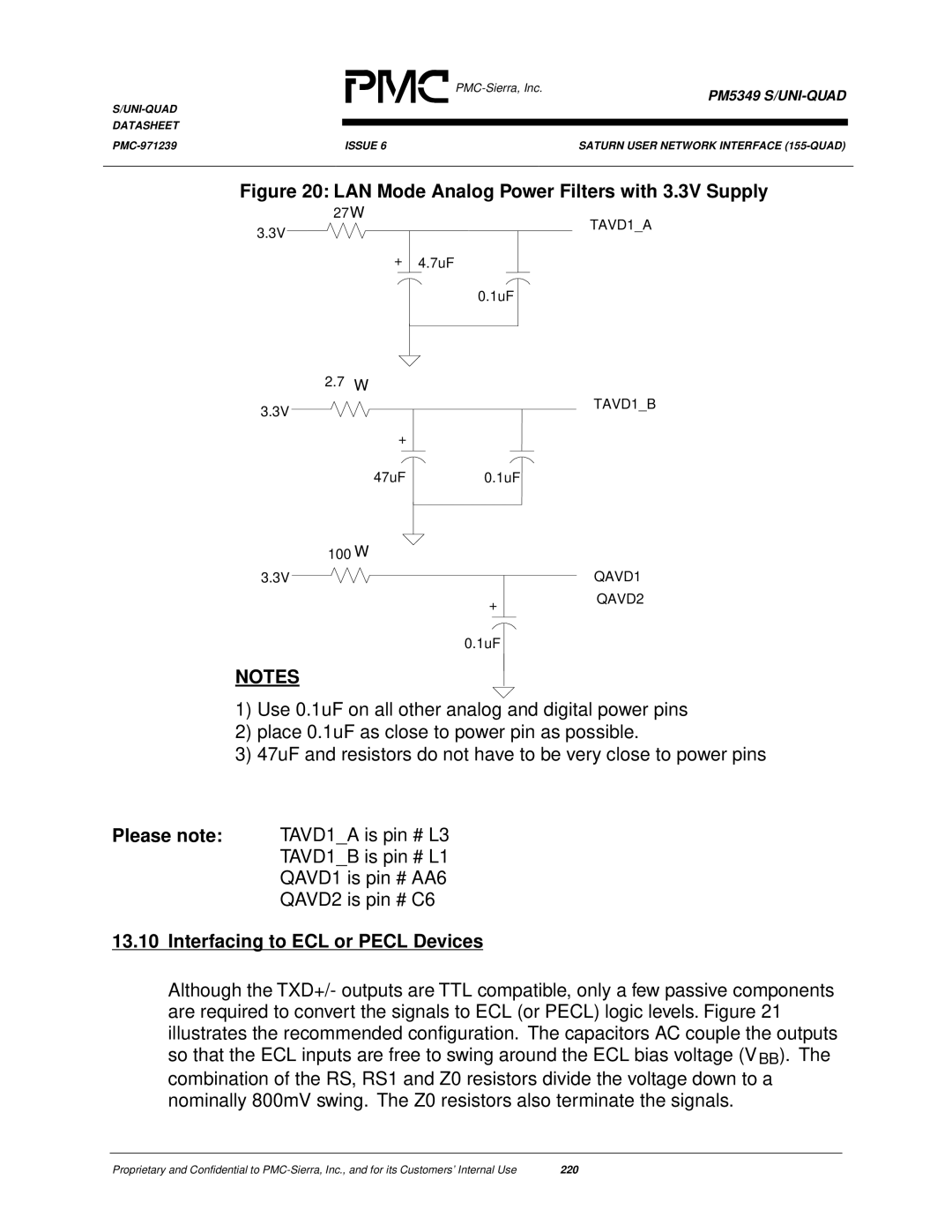
Figure 20: LAN Mode Analog Power Filters with 3.3V Supply
27Ω
3.3V
TAVD1_A
+4.7uF
0.1uF
2.7Ω
3.3V | TAVD1_B |
| |
+ |
|
47uF | 0.1uF |
100Ω
3.3VQAVD1
+ | QAVD2 |
| |
0.1uF |
|
NOTES
1)Use 0.1uF on all other analog and digital power pins
2)place 0.1uF as close to power pin as possible.
3)47uF and resistors do not have to be very close to power pins
Please note: TAVD1_A is pin # L3
TAVD1_B is pin # L1
QAVD1 is pin # AA6
QAVD2 is pin # C6
13.10Interfacing to ECL or PECL Devices
Although the TXD+/- outputs are TTL compatible, only a few passive components are required to convert the signals to ECL (or PECL) logic levels. Figure 21 illustrates the recommended configuration. The capacitors AC couple the outputs so that the ECL inputs are free to swing around the ECL bias voltage (VBB). The combination of the RS, RS1 and Z0 resistors divide the voltage down to a nominally 800mV swing. The Z0 resistors also terminate the signals.
Proprietary and Confidential to | 220 |