DATASHEET
PM5349 S/UNI-QUAD
ISSUE 6 | SATURN USER NETWORK INTERFACE | |
|
|
|
14 FUNCTIONAL TIMING
All functional timing diagrams assume that polarity control is not being applied to input and output data and clock lines (i.e. polarity control bits in the
14.1 ATM Utopia Level 2 System Interface
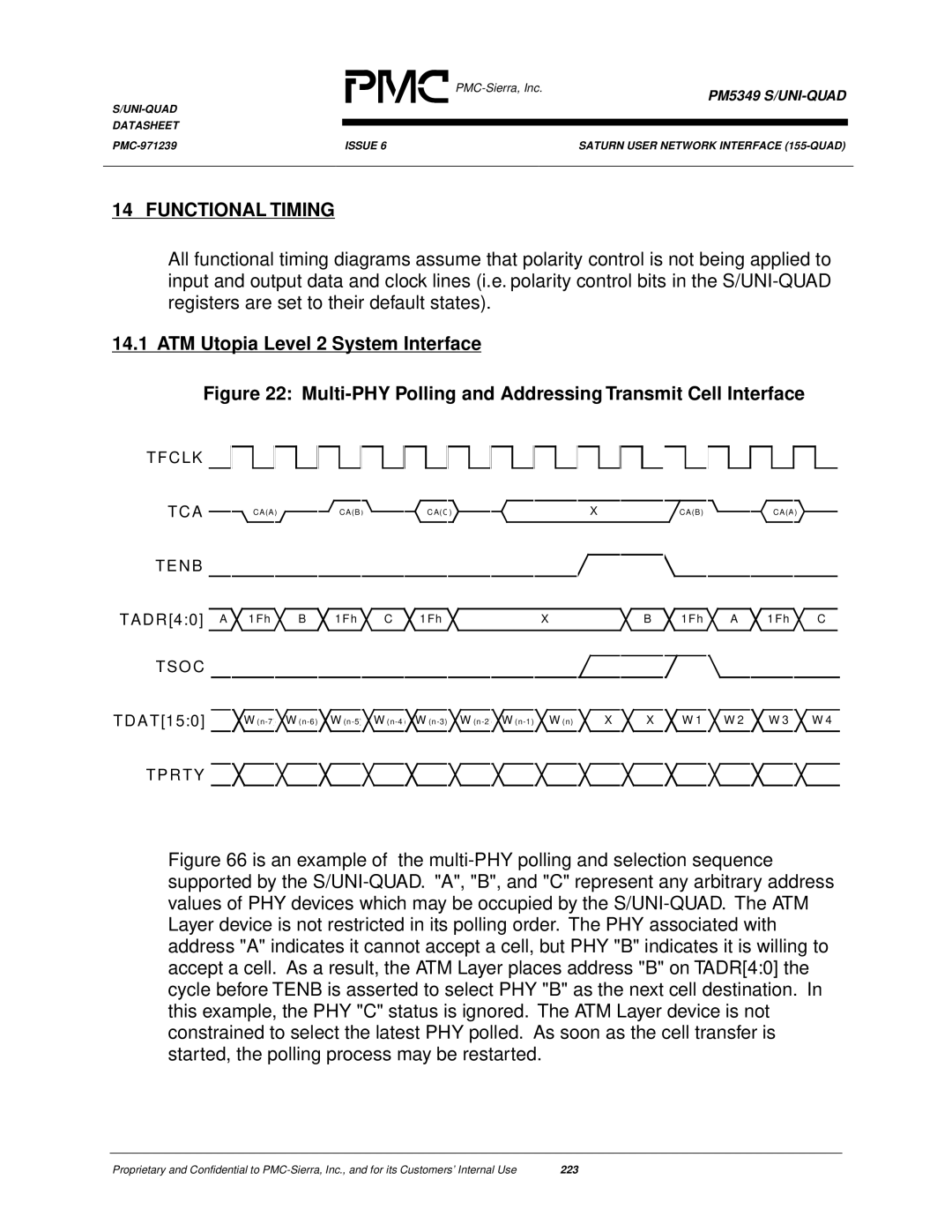
Figure 22: Multi-PHY Polling and Addressing Transmit Cell Interface
TFCLK
TCA |
|
|
| C A(A) |
|
|
|
|
|
| CA(B) |
|
|
|
|
| CA(C) |
|
|
|
|
|
| X |
|
|
|
| CA(B) |
|
|
|
| CA(A) |
|
|
| ||||||||||
|
|
|
|
|
|
|
|
|
|
|
|
|
|
|
|
|
|
|
|
|
|
|
|
|
|
|
|
|
| ||||||||||||||||||
TENB |
|
|
|
|
|
|
|
|
|
|
|
|
|
|
|
|
|
|
|
|
|
|
|
|
|
|
|
|
|
|
|
|
|
|
|
|
|
|
|
|
|
|
|
| |||
|
|
|
|
|
|
|
|
|
|
|
|
|
|
|
|
|
|
|
|
|
|
|
|
|
|
|
|
|
|
|
|
|
|
|
|
|
|
|
|
|
|
| |||||
|
|
|
|
|
|
|
|
|
|
|
|
|
|
|
|
|
|
|
|
|
|
|
|
|
|
|
|
|
|
|
|
|
|
|
|
|
|
| |||||||||
TADR[4:0] A | 1Fh |
|
|
| B |
|
| 1Fh |
|
| C |
|
| 1Fh | X | B |
|
|
| 1Fh | A | 1Fh | C | ||||||||||||||||||||||||
TSO C |
|
|
|
|
|
|
|
|
|
|
|
|
|
|
|
|
|
|
|
|
|
|
|
|
|
|
|
|
|
|
|
|
|
|
|
|
|
|
|
|
|
|
|
|
|
|
|
|
|
|
|
|
|
|
|
|
|
|
|
|
|
|
|
|
|
|
|
|
|
|
|
|
|
|
|
|
|
|
|
|
|
|
|
|
|
|
|
|
|
| |||||
|
|
|
|
|
|
|
|
|
|
|
|
|
|
|
|
|
|
|
|
|
|
|
|
|
|
|
|
|
|
|
|
|
|
|
|
|
|
|
|
|
|
|
|
|
|
|
|
TDAT[15:0] |
|
| W |
|
| W |
|
| W |
|
| W |
| W |
| W (n) X | X |
|
|
| W 1 | W 2 | W 3 | W 4 | |||||||||||||||||||||||
|
|
|
|
|
|
|
|
|
|
|
|
|
|
|
|
|
|
|
|
|
|
|
|
|
|
|
|
|
|
|
|
|
|
|
|
|
|
|
|
|
|
|
|
|
|
|
|
TPRTY
Figure 66 is an example of the multi-PHY polling and selection sequence supported by the S/UNI-QUAD. "A", "B", and "C" represent any arbitrary address values of PHY devices which may be occupied by the S/UNI-QUAD. The ATM Layer device is not restricted in its polling order. The PHY associated with address "A" indicates it cannot accept a cell, but PHY "B" indicates it is willing to accept a cell. As a result, the ATM Layer places address "B" on TADR[4:0] the cycle before TENB is asserted to select PHY "B" as the next cell destination. In this example, the PHY "C" status is ignored. The ATM Layer device is not constrained to select the latest PHY polled. As soon as the cell transfer is started, the polling process may be restarted.
Proprietary and Confidential to | 223 |