|
| PM5349 |
| |
|
|
| ||
|
|
|
| |
DATASHEET |
|
|
|
|
|
|
|
| |
|
|
|
| |
ISSUE 6 |
| SATURN USER NETWORK INTERFACE |
| |
|
|
|
|
|
Pin Name | Type | Pin | Function | |
|
| No. |
| |
|
|
|
| |
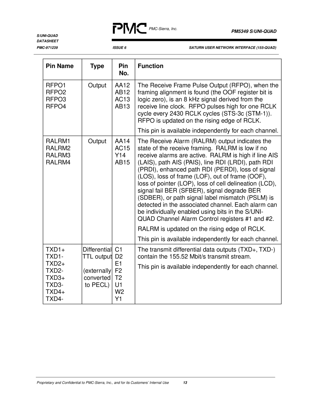
RFPO1 | Output | AA12 | The Receive Frame Pulse Output (RFPO), when the | |
RFPO2 |
| AB12 | framing alignment is found (the OOF register bit is | |
RFPO3 |
| AC13 | logic zero), is an 8 kHz signal derived from the | |
RFPO4 |
| AB13 | receive line clock. RFPO pulses high for one RCLK | |
|
|
| cycle every 2430 RCLK cycles | |
|
|
| RFPO is updated on the rising edge of RCLK. | |
|
|
| This pin is available independently for each channel. | |
|
|
|
| |
RALRM1 | Output | AA14 | The Receive Alarm (RALRM) output indicates the | |
RALRM2 |
| AC15 | state of the receive framing. RALRM is low if no | |
RALRM3 |
| Y14 | receive alarms are active. RALRM is high if line AIS | |
RALRM4 |
| AB15 | (LAIS), path AIS (PAIS), line RDI (LRDI), path RDI | |
|
|
| (PRDI), enhanced path RDI (PERDI), loss of signal | |
|
|
| (LOS), loss of frame (LOF), out of frame (OOF), | |
|
|
| loss of pointer (LOP), loss of cell delineation (LCD), | |
|
|
| signal fail BER (SFBER), signal degrade BER | |
|
|
| (SDBER), or path signal label mismatch (PSLM) is | |
|
|
| detected in the associated channel. Each alarm can | |
|
|
| be individually enabled using bits in the S/UNI- | |
|
|
| QUAD Channel Alarm Control registers #1 and #2. | |
|
|
| RALRM is updated on the rising edge of RCLK. | |
|
|
| This pin is available independently for each channel. | |
|
|
|
| |
TXD1+ | Differential | C1 | The transmit differential data outputs (TXD+, | |
TXD1- | TTL output | D2 | contain the 155.52 Mbit/s transmit stream. | |
TXD2+ |
| E1 | This pin is available independently for each channel. | |
TXD2- | (externally | F2 | ||
| ||||
TXD3+ | converted | T2 |
| |
TXD3- | to PECL) | U1 |
| |
TXD4+ |
| W2 |
| |
TXD4- |
| Y1 |
| |
|
|
|
|
Proprietary and Confidential to | 13 |