ViewStation User Guide
Page
Important Information
FCC Notice
Plug Acts as Disconnect Device
Underwriters Laboratories Statement
Page
Contents
Using the ViewStation
Using the ViewStation with a PC
Troubleshooting
System Information and Diagnostics
Network Address Translation
Video and Audio Input and Output Levels
Optional Equipment Configuration
Isdn Information
Glossary
ViewStation User Guide Xii
Preface How To Use This Guide
ViewStation Basics
Icon
Function
Figure a Conventions Flow Example
Usability Conventions
Preface How To Use This Guide ViewStation User Guide Xvi
What You Need to Get Started
Getting Started
What’s in the Box
Power Source
Television Monitors
NT-1 Device
Setting Up the ViewStation
Using the Remote Control
Placing the ViewStation
Connecting the ViewStation to the Isdn or DCP Network
ViewStation H.323 with Avaya DCP
ViewStation H.323 with Quad BRI
ViewStation
DCE
Connecting the ViewStation H.323 with V.35 to a Network
LED Activity on the V.35 Network Interface Module
Connecting the ViewStation to an Ethernet LAN
Setup Common to all ViewStations
Initial System Configuration
ViewStation Main Welcome Screen
ViewStation System Name Screen
Select Country Screen
LAN/Internet Calls H.323
Call Preference Screen For Isdn
DCP Call Preference Screen
For ViewStation H.323 with Video Calls
V.35 Call Preference Screen
10. H.323 Setup Screen
11. ViewStation H.323 Gatekeeper Screen
RS-366 Dialing
12. V.35 Video Network Screen
Ports Used
711u 711A 722-56
Video Protocol
15 fps 10 fps Fps
722-48 Off
15. Dialing Speeds Screen
16. Isdn Video Numbers Screen
17. DCP Video Numbers Screen
18. Auto Detect SPIDs Screen
20. Isdn Switch Protocol Screen
Icon Meaning
Network Status Indicators
Communications, on
Using ViewStation Help
Using the ViewStation Help
24. Help Screen
Technical Support
25. Technical Support Help Screen
User Setup
Optional Configurations
Optional Configurations
Chapter
Admin Setup Screen
Admin Setup
General Setup
General Setup Screen
Area Code Required
Allow Dialing Disabled Screen
Not Checked Prevents changes to the User Setup settings
On the Imux screen System Info Admin Setup Video
Network Setup screen System Info Admin Setup Video
Video Network
Imux Inverse Multiplexer
Inverse Multiplexer Information Screen
Numbers
Isdn Video Numbers Screen
Service Profile Identifier
10. Auto Detect SPIDs Screen
Audio Quality
11. Audio Quality Screen
Advanced Dialing
12. Advanced Dialing Screen
Dialing Speeds
14. Isdn Video Network
Isdn Video Network
15. Call Preference Screen
Call Preference
16. Network Setup Screen MP Enabled ViewStations Only
Multi-Point Setup MP Enabled ViewStations
17. Inverse Multiplexer Information Screen
18. DCP Video Numbers Screen
19. Audio Quality Screen
20. Advanced Dialing Screen
Area Code Choose the Area Code or STD Code where
DCP Video Network
DCP Video Calls H.320 LAN/Internet Calls H.323
24. ViewStation 128 Isdn Network Setup Screen
Multi-Point Setup MP Enabled ViewStations only
25. Dialing Speeds Screen
Chapter
ViewStation H.323 with
26. V.35 Network Setup Screen
Video Network for
LAN/Intranet Calls H.323
Display IP Dialing Extension
Broadcast Mode
29. Broadcast Mode Screen
Video Format
30. Advanced V.35 Dialing Screen
Video Numbers
31. Video Numbers Screen for
Advanced V.35 Setup
LAN/Internet
LAN/H.323
34. LAN & Intranet Screen
H.323 Setup screen System Info Admin Setup
Setup
36. H.323 Setup Screen
Setup
37. Video Phone Screen with Isdn Selected
38. Video Phone Screen with IP Selected
Gateway
39. Gateway Screen
Gatekeeper
40. Gatekeeper Screen
Dialing Speeds
41. Isdn and IP Dialing Speeds Screen
Quality of Service QoS and Firewalls
Snmp
Snmp Setup screen System Info Admin Setup LAN
Enable Snmp
Global Address
128 Server Preferences Private NET
Number Dialing Rules
44. Global Address Screen ViewStation H.323
45. Global Address Screen ViewStations with Isdn and DCP
46. Global Address for ViewStation
Server
Preferences
Register this System When Powered On
ViewStation with Quad BRI, V.35, Avaya DCP, and MP
Display Global Addresses
48. GAB Preferences Screen
ViewStation H.323
Private NET
Private Net feature System Info Admin Setup LAN/H.323
Gateway Number
Dialing Rules
50. Dialing Rules 1 Screen
Call From Call To Type of Call Placed
Public Network Access Use Public Network
51. Dialing Rules 2 Screen
Global Management
52. Global Management Screen
GMS Setup
53. Global Management Screen
Daylight Savings Time DST
Data Conference screen System Info Admin Setup
Global Management Information
Data Conference
Mute Auto Answer Calls
Telephone & Audio
56. Telephone & Audio Screen
VCR Audio Out Always On Except ViewStation
Snapshot Timeout
Video&Camera screen System Info Admin Setup
Video/Camera
Acoustic Plus
58. Video & Camera Screen
Chapter
59. Security Screen for All Models Except
Security
60. Security Screen for the ViewStation
Software Information
Software/Hardware
System Options
Hardware Information
Main Calling Screen
Placing and Answering Calls
ViewStation 128 Main Calling Screen
ViewStation Network Line Indicators
ViewStation Main Calling Screen 512 MP Shown
Placing a Video Call
Video Phone Screen
Placing a Video Call Manually
Icon Appearance Indication
Call Hangup Choices Screen
Placing a Video Call Using Speed Dial
Speed Dial Screen
Using the Address Book
Placing a Video Call From the Web lnterface
Adding New Entries to the Address Book
Address Book Screen
New Address Book Entry Screen for ViewStations with MP
10. Multi-Site Meeting Screen
Editing an Existing Entry in the Address Book
11. Add / Change Entry Screen
Deleting an Entry from the Address Book
12. Send Address Book Screen
Transferring an Address Book
Using Multi-Point Address Book Entries
Using the Global Address Book
Creating a multi-point address book entry
Placing a Video Call Using the Address Book
13. Address Book Screen
Placing a Video Call from the Web Interface
Placing a Telephone Call
Placing Telephone Calls with the ViewStation
Manual
Answering a Video Call
Auto-Answer
Placing Multi-Point Calls ViewStation MP Only
Polycom, Inc 115
15. Address Book Screen
Adding a Telephone Call to a Video Call
16. Telephone Screen
17. Call Hangup Choices Screen
Multi-Point Viewing Modes
Using Chair Control in a Multi-Point Call
18. Chair Control Screen
Actions Any Site Can Perform
Actions Only The Chair Control Site Can Perform
Using a ViewStation with a StreamStation
19. Main ViewStation Menu with StreamStation Icon
Starting a Webcast
21. Streaming Call Screen
Ending a Webcast
22. ViewStation Main Menu with StreamStation
Displaying ChatBack Messages
Selecting ViewStation Cameras
Adjusting Cameras and Sound
24. Camera Near Icon
Pan, Tilt, and Zoom for the ViewStation Camera
Setting Camera Presets
Automatic Voice Tracking
Automatic Tracking of Camera Presets
Adjusting Sound
Sending Snapshots
Positioning Microphone Pods
Snapshot Timeout
Using Optional Equipment
Polycom, Inc 131
ViewStation User Guide 132
Using the ViewStation with a PC
Ethernet LAN
Connecting The PC to a LAN Through the ViewStation
PC Network Properties
Network Screen for Windows
Connecting The ViewStation to a Stand-Alone PC
Enable system to be a Dhcp server
For Windows 9X/NT
For Windows 2000/ME
PC TCP/IP Network Screen
Select and View a Presentation
Using the ViewStation Web Interface
Select a Presentation Screen
On the PC
PcPresent Screen
Open Presentation Screen
Available Presentations Screen
On the ViewStation
11. Thumbnail of Slides in the Presentation Directory
Viewing Snapshots from the ViewStation
Sending Snapshots to the ViewStation
Button Action
Select View a Presentation
Closed Caption
Accessing and Using Closed Caption
Usage Information and Restrictions About Closed Caption
Using Microsoft NetMeeting
13. About Windows NetMeeting Dialog Box
PC and select Help About Windows NetMeeting.
NetMeeting Application Sharing
Video Calls with NetMeeting
System Information and Remote Management
Place a Call icon
Placing a Call from the ViewStation Web Interface
15. Place a Call from the Web Interface Screen
16. Placing a Call
Near Site
18. Manual Dial Screen
ViewStation Web Interface Icons
System Info Admin Setup General Setup
System Info Admin Setup Video Network
System Info Admin Setup Video Network Imux
System Info Admin Setup Data Conference
System Info Admin Setup Phone/Audio
System Info Admin Setup Video/Camera
System Info Admin Setup Software / Hardware
System Info Admin Setup Software / Hardware System Options
System Info Diagnostics
System Info Diagnostics Advanced Stats
System Info Diagnostics Color Bar
System Info Diagnostics Audio Generate Tone
System Info Diagnostics Near End Loop
Web Interface Icon ViewStation Counterpart
Restart System icon is
Numbers
ViewStation User Guide 160
System Info Admin Setup Video Network Imux Advanced Dialing
System Info Admin Setup LAN/H.323 LAN/Intranet
System Info Admin Setup Video Network Video
System Info Admin Setup Global Address Global
System Info Admin Setup Global Management
Preferences
System Info Admin Setup LAN/H.323 Snmp
System Info Admin Setup Global Management Info
Downgrading Software
ViewStation Software
Upgrading Software
Upgrading Software over Isdn
Upgrading Software over the LAN
19. Software Update Screen
20. System Information Dialog Box
Using Visual Concert PC
Concert PC User Guide
ViewStation User Guide 170
System Information
System Information and Diagnostics
System Info Admin Setup Software/Hardware Software
Diagnostics
Network Stats
Advanced Stats
Call Status
Audio
Color Bar
Near End Loop
Far End Loop
Reset System
ViewStation User Guide 176
Symptom Cause Solution
General Problems
Generate Tone screen under
Audio
Polycom, Inc 179
Video
Diagnostics Network Stats
Symptom Cause
See Isdn Information on
Network and Communications
Info Admin Setup Video
Imux
LAN/Intranet
Presentations
Polycom, Inc 187
System Control
Low battery icon on
Setting up NAT
Before You Start Configuring NAT
Appendix a
Audio Levels
Video Levels
Video Output Levels
Video Input Levels
Audio Input Levels
Serial Interface Control Signals
Signal Direction Description Configuration Option Cable Pin
General V.35 Information
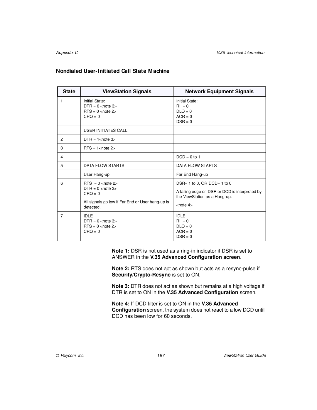
State ViewStation Signals Network Equipment Signals
State Machine
Dial Out State Machine
Security/Crypto-Resync is set to on
In-bound Call State Machine
ViewStation User Guide 196
Nondialed User-Initiated Call State Machine
Nondialed Network-Initiated Call State Machine
Crypto Resync
Figure C-1.V.35 Y Cable Pinout
Cabling Diagram and Schematic
Figure C-2.ViewStation V.35 Cable Diagram
ViewStation User Guide 202
Sample NT-1 Settings
Switches Configuration Termination
Status
Switches
Isdn Errors
Isdn Switches
Switch Type SPIDs Allocated
Code Cause Definition
ViewStation User Guide 206
Polycom, Inc 207
ViewStation User Guide 208
Polycom, Inc 209
ViewStation User Guide 210
StreamStation Configuration
Optional Equipment Configuration
Troubleshooting Hints
Using a ShowStation IP
ViewStation User Guide 214
ABC
ARJ
BRI
DEF
DSL
FTP
Ghijk
ISP
Glossary
LMN
OPQ
RST
UVW
XYZ
Index
Creating a multi-point address
Name when calling this system
133
88, 131
20, 21