FCD-IPM
Page
FCD-IPM
International Headquarters RAD Data Communications Inc
Limited Warranty
General Safety Instructions
Please observe the following precautions
Connection of AC Mains
General Safety Practices
Connection of DC Mains
Ports Safety Status
Connection of Data and Telecommunications Cables
Electromagnetic Compatibility EMC
Conventions
Measures
Page
Installing and Operating FCD-IPM
To install FCD-IPM
Quick Start Guide
Contents
Setup Menu
Configuration
View Menu
Troubleshooting and Diagnostics
View Menu Outline
FCD-IPM Main Menu
Firewall Rules Menu
Routing Tables Menu Bridge Table
Interface Routing Bridging Mode Menu
56. E1 Setup Menu
41. T1 Setup Menu
WAN Economy Menu Outline
Link Settings
Interval Parameters
Device Security Identity
Overview
Versions
E1/T1 over fiber optic links with interfaces
Backup
Applications
Features
Physical Description
Functional Description
Main Link and Sublink Characteristics
FCD-IPM Functional Block Diagram
E1 over Shdsl
IO Data Channel Interfaces
System Timing Considerations
AWG line
Bridging
Time Slot Handling
Integrated Router
IP Router
Protocols
Management
Management Using Dedicated Time Slot DTS
Unbalanced interface Two BNC coaxial
Compliance ITU G.703, G.704, G.706, G.732 Diagnostics
Zero Suppression
Framing Options
For direct connection to a 2-wire telephone
Type Wire unconditioned dedicated line Line Coding
Impedance 135Ω Connector RJ-45 Protection ITU K.21, UL1950
Range
Routing
WAN Protocols
Types
Link error red
Interface Options Nm LED Nm laser diode Connectors
Power indicator green
RED alarm red T1 only
RM-34 for 19-inch Rack
Power consumption 12W
General
Supply voltage
Introduction Technical Specifications
Enable free airflow
Site Requirements & Prerequisites
Installation and Setup
Package Contents
Equipment Needed
Fuses
Location of Internal BAL/UNBAL Jumpers
E1/T1 Link Connections
Interfaces and Connections
IO Data Channel Connections
DC Power Connection
Connecting the Power
AC Power Connection
Control Port Connection
Installation and Setup
Front Panel Indicators
Indicators
Introduction
Front Panel Indicator Functions
Object Description Function
Turning On
Rear Panel Indicators
Operating Instructions
Normal Indications
Operation
Connecting the Terminal Emulator
Connecting to the Ascii Terminal
Fault Indications
Turning Off
To initiate the login message
Password Protection
To setup the terminal
Press Enter several times
Chapter Configuration
Main Menu has the following options
Main Menu
Quick Setup Menu
To access the Quick Setup Menu
To choose an option from the Main Menu
To view the options
Quick Setup Parameters
To configure the setup parameters
To enter new information
Quick Setup Parameters
Parameters Type Options
Quick Setup for T1 PPP, IP
Quick Setup Menu Examples
Quick Setup
Quick Setup for E1 PPP, IP + Isdn Backup, 128K, PPP, IP
3shows the Quick Setup menu for E1
Set this parameter for the WAN configuration
WAN Settings
WAN Parameters
PPP
Default PPP
RFC-1490
Set the parameters in this section for each LAN connection
LAN Settings
LAN Parameters
Setting up the IP Mask
Isdn Settings
Isdn Settings
Frame Relay Settings
Dlci Number
Two settings that must be made
Async Settings
Security Settings
V.24 Async Settings
To access the Security Setup Menu
Security Setup Menu
Security Setup options are described below
Enabling Snmp Access
Device Access Restriction
Enabling Telnet Access
Changing Login Password
From the Main menu, select option 2, Security Setup
Supervisor Access
To set a Monitor Supervisor Password
Firewall Option
Firewall
To define the Solid Firewall rules
Select interface LAN Select direction outbound
Configuring Firewalls
IP Address Translation NAT
Firewall Rules
IP Address Translation NAT Settings
Transparent PAT Port Address Translation
To access the Advanced Menu
Advanced Setup Menu
Setup Menu
Main Menu, press Advanced Menu appears refer to Figure
Device Control Menu
To access the Device Control menu
Options in the Device Control menu are described below
Software Download
Select this option to download a new software version
To download a new software version via Tftp server
Download from Tftp Server
Select option 1 from the Software Download menu
Upload Device Parameters to Tftp Server
Xmodem via Control Port Boot Manager
To upload device parameters
Terminal Type
Reset Options
Download Device Parameters from Tftp Server
To download device parameters
To access the View Menu
View Menu
Configuration
24. View Menu
SHDSL+SUB
O1 FXS O2 FXS
Select this option to display different routing tables
Interface Connections
Routing Tables
Options in the Routing Tables menu are described below
IP Routing
Bridge
IP Interfaces
Details the routing interfaces information
IPX NET IPX Node Type Hops Ticks Ageing Interface
IPX Routing
Select this option to display information on IPX routing
NET RIP
IPX Services
IP Address Pool Dhcp
Ospf Related Information
Area ID Type LS-ID Orig RTR SEQ NUM AGE Cksum
IP Address Prio State
F7FD
Shdsl Status and Statistics
To access the Shdsl Status screen
Statistics
Displaying the Shdsl Status
Data mode
Shdsl Status Screen Parameters
To display statistics for specific intervals
Displaying the Shdsl Statistics
Shdsl Statistics Parameters
Display Description
T1 Diagnostics
E1/T1 Diagnostics
To refresh or clear statistics
Interval Parameters
10. Interval Parameters
E1/T1 Alarms
E1/T1 Alarms Log File
Select this option to display the E1/T1 Alarms Log file
Interface Type Status Days Hours MIN SEC
Diagnostic Tools Menu
To access the Diagnostic Tools menu
To ping another host
49. Ping Terminal Screen
Advanced Menu, press Setup menu appears refer to Figure
To access the Setup menu
Options in the Setup menu are described below
Host Parameters Menu
To access the Host Parameters menu
Host Parameters
Tftp Radius
Device ID
Options in the Host Parameters menu are described below
Device ID
Device ID Parameters
IP Host
Current NEW
IP Host Parameters
Default Gateway
Snmp Manager Table
Tftp Trivial File Transfer Protocol
Tftp Parameters
Radius Authentication and Billing
11. Radius Menu
Radius Menu Parameters
Routing/Bridging Menu
To access the Routing/Bridging menu
Setup menu, press Routing/Bridging menu appears
Select this option to enter FCD-IPM routing information
Options in the Routing/Bridging menu are described below
Interface Routing/Bridging Mode
PPP
Interface Routing/Bridging Mode Menu Parameters
Slip Cslip
This option is only available for PPP link protocol
PPP Settings
PPP Settings
BOD
Can be defined in 4 ways see Table
Static Stations and Nets
Does not remove static entries from the routing tables
Static Stations and Nets
16. Router 2 set to Next Hop in FCD-IPM
IP Routings Settings
Interface Address
Maximum Transmit Unit
IP Address Pool Setting Dhcp
Routing Protocol
Dhcp Relay
Select this option to define IP address information
FCD-IPM supports all these mechanisms simultaneously
IP Address Pool
Dhcp
PC Remote Access
10. IP Address Pool Settings
Nothing
Ospf Settings
FCD-IPM
Static Only RIP Only Static & RIP
Link 1/CH1
Interfaces Area ID
Link 1/CH2
Normal
12. Ospf Areas Setup
Ospf Summaries Setup
Stub
13. IPX Routing Settings
IPX Routing Settings
IPX router
RIP/SAP Mode
LAN RIP/SAP
Station Ageing
29. Station Aging Menu
Setup menu, press Interface Parameters menu appears
To access the Interface Parameters menu
Interface Parameters Menu
Link Settings Menu
31. Interface Parameters
Answer & Originate
14. Link Settings
ON, Ignore
Odd
Shdsl Settings
Even
15. Shdsl Parameters
To configure the Shdsl parameters
Shdsl Parameters
STU-C
Shdsl Loops
To access the Shdsl Loops menu
16. Shdsl Loops
E1/T1 Settings
Loopback
38. FCD-IPM with an E1/T1 Interface
T1 Features
E1 Features
O1 SUB T1
T1 Setup Menu
17. T1 Setup Parameters
O2 SUB T1 FIX SUB T1
Time Slots Mapping
TS2 Data LINK1
T1 Time Slots Mapping Link
TS1 Data LINK1
TS3
Loopback options are
Disabled
Loopback
45. Remote Analog Loopback for T1 and Sub T1 Links
48. Local Analog Loopback
49. Local Analog Loopback for T1 and Sub T1 Links
B7ZS
T1 Link Parameters
ESF
B8ZS
T1 Parameters Link1 Parameters
Additional Cards Parameters
FCD-IPM has optional voice capabilities
Voice
Fix Voice O1Voice O2 Voice
Voice Parameters
Bit
52. FXO Voice Interface
FXO Voice Interface
Ring Detection to T1 On
This parameter specifies the interface type
This parameter is set to
Voice Interface
Type
Typical screen is shown in Figure
Time Slots for Voice Ports
Select this parameter to set a unique IP address
Management Time Slot Number
Management Host IP Address
AIS
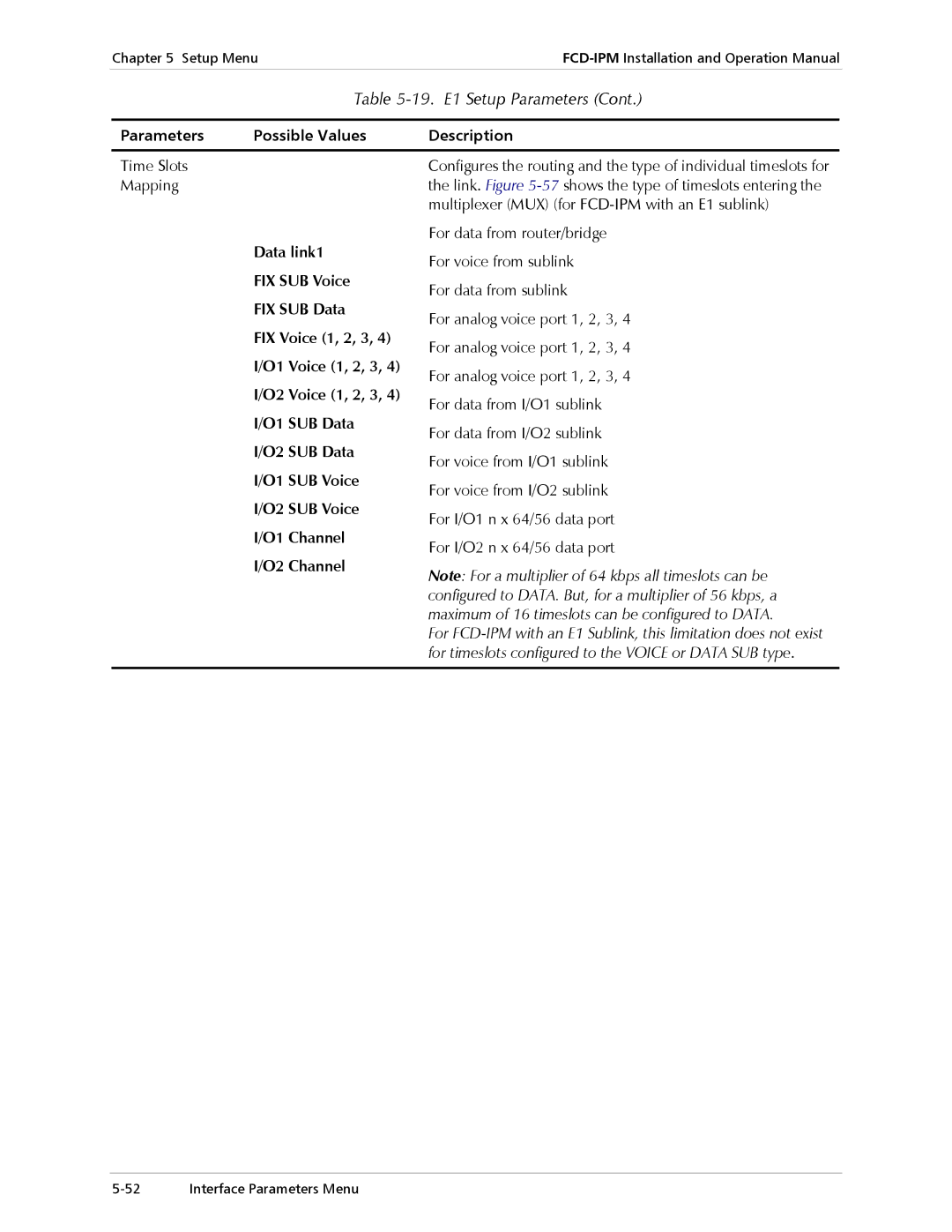
19. E1 Setup Parameters
E1 Setup Menu
This section describes the parameters in the E1 Setup menu
O1 SUB E1
Time Slots Mapping
TS4 O1 Voice
TS2 FIX SUB-VOICE
TS3 FIX SUB-DATA
TS5 O1 Voice
59. Remote Analog Loopback
60. Remote Analog Loopback for E1 and Sub E1 Links
Select this option to configure the parameters that follow
E1 Link Parameters
20. E1 Link1 Parameters
Ccitt
Coding Law
TX/RX Gains
Law coding for E1 links
On/off hook from the E1 on
Default Abcd to the E1
On/off hook to the E1 on
65. FXO Voice Interface
Law coding for E1 links On/off hook from the E1 on
Out of Service Method
Signaling Feedback
Ring Detection to E1 on
RX/TX Gains
Interface Type
Law Coding for E1 links Signal from the E1 on
Refer to Table Typical screen is shown in Figure
67. E1 Time Slots Mapping Link1 Screen Alarms Filter
Management Time Slot Number
Isdn Settings Menu
Management Host IP Address
22. Answering Mode Parameters
Isdn has the following features
21. Dialing Mode Parameters
To activate the Isdn line Choose the Isdn protocol
23. Local Number for Dialback
70. Dialback Phone Number
Frame Relay Dlci Settings
Link Dlci State CIR Excess Throughput
Implementing Frame Relay
73. Frame Relay Options in the Advanced Menu
24. Frame Relay Link Parameters
Enquiry frames in a sliding monitored events window
74. Polling Intervals
25. Frame Relay Dlci Parameters
Frame Relay Dlci Parameters
Dlci
To access the Access Control menu
Access Control Security Menu
Select this option to perform security operations
78. Access Control Menu
79. External Access Security Menu
26. External Access Security Parameters
Radius
Device Security Identity PPP only
FCD IPM
Link Host
Login Script Setup
Security Host/Guest PPP only
Current Script for Link
Command codes are described in Table
Command Code
28. Command Codes
29. Example of Argument
Argument
Code to wait/send Control Sequence
To access the WAN Economy menu
WAN Economy Menu
Filters
Options in the WAN Economy menu are described below
86. Action of a Quick Filter
Forwarding
Blocking
Multiple Filters
Quick Filters
Toggle between Block and Forward
To configure the broadcast control
Factory default Block Propagation
No Filters
Add Filters Menu
Advanced Filters
Choose Advanced Filter
True-False Menus
30. Add Filters Menu Terms
Advanced Filter Parameters 31. Advanced Filter Parameters
FTP
MAC
NET
WWW
TCP
Saving Filter Parameters
UTP
Icmp
Connection on Demand
91. Connection On Demand Menu
You need to configure Start Connection Terminate Connection
32. Connection On Demand Parameters
Following examples demonstrate how COD can be used
Example
93. Any Frame Starts a Connection
94. Limiting Access to a Specific PC
Spoofing
95. Manual Connection
Enabled Enabled COD
33. IP/IPX Spoofing Parameters
To access the Factory Default menu
Factory Default Options
Factory Default Options
Setup Menu Factory Default Options
General Troubleshooting
General Troubleshooting
E1/T1 and Voice Troubleshooting
E1, T1 and Voice Troubleshooting
IP Connection to WAN Troubleshooting
Router Connections Troubleshooting
Router Connections Troubleshooting
IP connection to LAN is Down
Troubleshooting and Diagnostics
Troubleshooting and Diagnostics
Interface Signal List Female Connectors
Table A-1. Interface Signal List Female Connectors
DTE DTR
RS-530 21 / 15-pin
RS-530 RS-449/V.36 37-pin
E1 over Shdsl Line Connector
E1/T1 Connectors
Pin Designation Direction Function
Table A-3. Control Cable RJ-45 to DB-9 Connection DCE
Control Cable Connector
Control cable connection pinout is provided in Table A-3
RJ-45 DB-9
Table A-5. Fiber Optic Interface Specifications
Isdn Connector
Isdn connector pinout is provided in Table A-4
Fiber Optic Interface
Table A-6 RJ-45 E&M Connector Wiring
E&M Connector
FXO/FXS Connector
Table A-7
To access Boot manager via Software Download menu
Accessing Boot Manager
Access via Software Download Menu
Preface
Boot Manager Menu
Rescue
Step
Load New Software
Partitions Status
Immediately after the change
Erase Configuration
Run Backup Partition
Reactivate Backup Partition
Duplicate Active Partition
Set Baud Rate
Immediately after performing the change
Appendix B Boot Manager Boot Manager Menu
Snmp Operations
Snmp Environment
Snmp Principles
This section describes the Snmp environment
Management Information Base
MIB Structure
MIBs Supported by the FCD-IPM Snmp Agent
Management Domains Under Snmp
Snmp Communities
Authentication
Trap Configuration
Snmp Configuration
Community Configuration
Indexing Convention
Snmp Traps
Supported Traps
Appendix D Glossary
Appendix D Glossary
Appendix D Glossary
Appendix D Glossary
DC Power Supply Connection Terminal Block Connector
DC Power Supply Wire Voltage Polarity
TB Plug with Captive Screws optional
Excellent Good Fair Poor Very Poor
Manual Name FCD-IPM Publication Number 702-200-08/03
Manual as a whole What did you like about the manual?
Page
Illogical flow of information
Difficulty in finding needed information
Missing information
Style spelling, grammar, references, etc
Page
Page
International Headquarters
Headquarters