CONNECTIONS
 Digital series connections
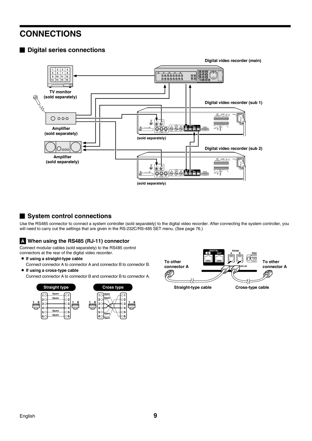
Digital video recorder (main)
1 | 2 | 3 | 4 |
|
|
|
|
|
|
|
|
|
|
|
5 | 6 | 7 | 8 |
| POWER | FULL |
| ALARM FULL |
| LOCK | ALARM | |||
|
|
|
|
|
|
| 1 | 2 | 3 | 4 | 5 | 6 | 7 | 8 |
9 | 10 | 11 | 12 |
|
|
| 9 | 10 | 11 | 12 | 13 | 14 | 15 | 16 |
13 | 14 | 15 | 16 |
|
|
|
|
|
|
|
|
|
|
|
TV monitor |
|
|
|
|
|
|
|
|
|
|
| |||
(sold separately) |
|
|
|
|
|
|
|
|
|
|
| |||
|
|
|
| MIC |
| AUDIO |
|
|
|
|
|
|
|
|
|
|
|
| IN | IN |
| OUT |
|
|
|
|
|
|
|
|
|
|
|
|
|
|
|
|
|
|
| VIDEO |
|
|
Amplifier |
|
|
|
|
|
| IN |
| LOOP OUT | OUT | ||||
PC Card SLOT |
|
|
|
|
|
|
|
|
|
| ||||
|
|
|
|
|
|
|
|
|
|
| ||||
(sold separately) |
| IN | LOOP OUT | OUT |
|
|
|
|
|
| ||||
|
|
|
|
|
|
|
|
| ||||||
|
|
|
|
|
|
|
|
|
|
| ||||
|
|
|
| (sold separately) |
|
|
|
|
|
| ||||
Amplifier |
|
|
|
|
|
|
|
|
|
|
| |||
(sold separately) |
|
| AUDIO |
|
|
|
|
|
|
|
| |||
|
|
|
| MIC |
|
|
|
|
|
|
|
|
| |
|
|
|
| IN | IN |
| OUT |
|
|
|
|
|
|
|
VIDEO
IN LOOP OUT OUT
PC Card SLOT ![]()
IN LOOP OUT OUT
(sold separately)
MENU | EXIT/OSD | PLAY/STOP | EN |
|
|
| TER |
ZOOM | SEARCH | STILL |
|
QUAD MULTI |
|
|
|
SEQUENCE | COPY | SHUTTLE LOCK |
|
MON2 PLUS |
|
|
|
REC/STOP | TIMER | ALARM |
|
Digital video recorder (sub 1)
|
|
| ALARM |
| CLOCK | AC IN |
|
|
| RESET |
| ADJUST | |
|
| ALARM ALARM |
|
| ||
|
| C IN | OUT C | IN OUT | FULL | |
DIGITAL | C A | B | C REMOTE C | NC NC C | C | |
| RS485 |
| SW | |||
OUT | SUB IN SUB OUT | RS232C |
| TERMINATE | OUT | |
|
| RS485 | ALL | ON |
|
|
|
| RESET |
|
| ||
|
|
|
| OFF |
|
|
|
| Digital video recorder (sub 2) | ||||||
|
|
|
| ALARM |
| CLOCK |
| AC IN |
|
|
|
| RESET |
| ADJUST |
| |
|
|
| ALARM ALARM |
|
|
| ||
|
| C | IN | OUT C | IN OUT |
| FULL | |
| DIGITAL | C A |
| B | C REMOTE C | NC NC | C | C |
IN |
|
| RS485 |
|
| SW | ||
OUT SUB IN SUB OUT | RS232C |
|
| TERMINATE |
| OUT | ||
|
| RS485 | ALL | ON |
|
|
| |
|
| RESET |
|
|
| |||
|
|
|
|
| OFF |
|
|
|
 System control connections
Use the RS485 connector to connect a system controller (sold separately) to the digital video recorder. After connecting the system controller, you will need to carry out the settings that are given in the
AWhen using the RS485 (RJ-11) connector
Connect modular cables (sold separately) to the RS485 control connectors at the rear of the digital video recorder.
•If using a
Connect connector A to connector A and connector B to connector B.
•If using a cross-type cable
Connect connector A to connector B and connector B to connector A.
|
| Straight type |
|
|
|
|
| Cross type |
|
|
| ||
|
| 1 | Spare | 1 |
|
|
|
| 1 | Spare | 1 |
|
|
|
| Spare |
|
|
|
| Spare |
|
| ||||
|
| 2 | 2 |
|
|
|
| 2 | 2 |
|
| ||
1 | 6 |
| 1 | 6 | 1 | 6 |
| 1 | 6 | ||||
3 |
| 3 | 3 |
| 3 | ||||||||
|
| 4 | Spare | 4 |
|
|
|
| 4 |
| 4 |
|
|
|
| 5 | 5 |
|
|
|
| 5 |
| 5 |
|
| |
|
| Spare |
|
|
|
| Spare |
|
| ||||
|
| 6 | 6 |
|
|
|
| 6 | 6 |
|
| ||
|
|
|
|
|
|
|
|
| |||||
|
|
|
|
|
|
| Spare |
|
| ||||
|
|
|
|
|
|
|
|
|
|
|
|
| |
| DIGITAL |
| RS485 |
| |
IN |
| OUT | A | B | RS23 |
To other |
| To other |
connector A | PHONE LINE | connector A |
English | 9 |