PART NAMES
 Front panel
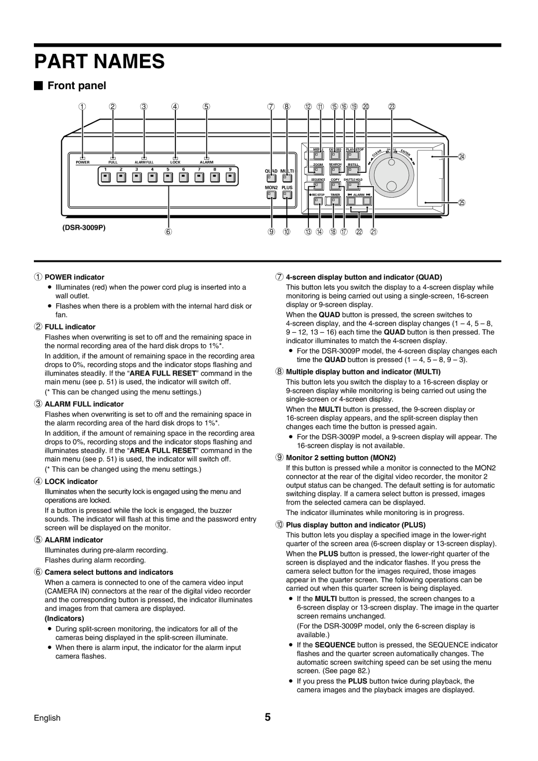
1 2 3 4 5 |
|
| 7 8 H G KL O P S |
|
| ||||||||||
|
|
|
|
|
|
|
|
| MENU | EXIT/OSD | PLAY/STOP | R | SHUTTLE | E |
|
|
|
|
|
|
|
|
|
|
|
|
| JOG |
| ||
|
|
|
|
|
|
|
|
|
|
|
| A |
| NT |
|
|
|
|
|
|
|
|
|
|
|
|
| E |
| E | T |
|
|
|
|
|
|
|
|
|
|
|
| L |
| R | |
|
|
|
|
|
|
|
|
|
|
|
| C |
|
| |
|
|
|
|
|
|
|
|
|
|
|
|
|
|
| |
POWER | FULL | ALARM FULL | LOCK |
| ALARM |
|
| ZOOM | SEARCH | STILL |
|
|
|
| |
|
|
|
|
|
|
|
|
|
|
|
|
| |||
1 | 2 | 3 | 4 | 5 | 6 | 7 | 8 | 9 | QUAD MULTI |
|
|
|
|
|
|
|
|
|
|
|
|
|
|
|
|
|
|
|
|
| |
|
| MON2 PLUS |
6 | 9 F | |
|
SEQUENCE COPY SHUTTLE HOLD
REC/STOP | TIMER | ALARM |
|
| U |
I J N M R Q
1POWER indicator
•Illuminates (red) when the power cord plug is inserted into a wall outlet.
•Flashes when there is a problem with the internal hard disk or fan.
2FULL indicator
Flashes when overwriting is set to off and the remaining space in the normal recording area of the hard disk drops to 1%*.
In addition, if the amount of remaining space in the recording area drops to 0%, recording stops and the indicator stops flashing and illuminates steadily. If the “AREA FULL RESET” command in the main menu (see p. 51) is used, the indicator will switch off.
(* This can be changed using the menu settings.)
3ALARM FULL indicator
Flashes when overwriting is set to off and the remaining space in the alarm recording area of the hard disk drops to 1%*.
In addition, if the amount of remaining space in the recording area drops to 0%, recording stops and the indicator stops flashing and illuminates steadily. If the “AREA FULL RESET” command in the main menu (see p. 51) is used, the indicator will switch off.
(* This can be changed using the menu settings.)
4LOCK indicator
Illuminates when the security lock is engaged using the menu and operations are locked.
If a button is pressed while the lock is engaged, the buzzer sounds. The indicator will flash at this time and the password entry screen will be displayed on the monitor.
5ALARM indicator
Illuminates during
6Camera select buttons and indicators
When a camera is connected to one of the camera video input (CAMERA IN) connectors at the rear of the digital video recorder and the corresponding button is pressed, the indicator illuminates and images from that camera are displayed.
(Indicators)
•During
•When there is alarm input, the indicator for the alarm input camera flashes.
74-screen display button and indicator (QUAD)
This button lets you switch the display to a
When the QUAD button is pressed, the screen switches to
9 – 12, 13 – 16) each time the QUAD button is then pressed. The indicator illuminates to match the
•For the
8Multiple display button and indicator (MULTI)
This button lets you switch the display to a
When the MULTI button is pressed, the
•For the
9Monitor 2 setting button (MON2)
If this button is pressed while a monitor is connected to the MON2 connector at the rear of the digital video recorder, the monitor 2 output status can be changed. The default setting is for automatic switching display. If a camera select button is pressed, images from the selected camera can be displayed.
The indicator illuminates while monitoring is in progress.
FPlus display button and indicator (PLUS)
This button lets you display a specified image in the
•If the MULTI button is pressed, the screen changes to a
(For the
•If the SEQUENCE button is pressed, the SEQUENCE indicator flashes and the quarter screen automatically changes. The automatic screen switching speed can be set using the menu screen. (See page 82.)
•If you press the PLUS button twice during playback, the camera images and the playback images are displayed.
English | 5 |