GENERAL SETTING
 NETWORK SET setting
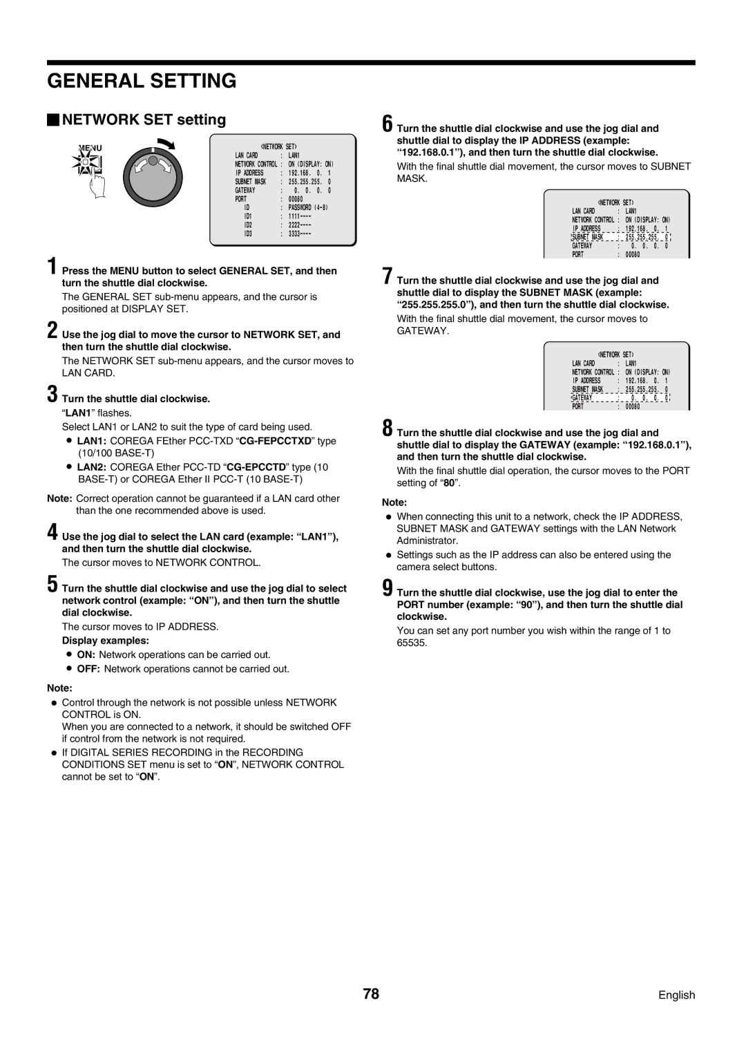
MENU | <NETWORK SET> |
|
| ||||
|
|
| LAN CARD | : | LAN1 |
|
|
|
|
| NETWORK CONTROL | : | ON (DISPLAY: ON) | ||
|
|
| IP ADDRESS | : | 192.168. | 0. | 1 |
|
|
| |||||
|
|
| SUBNET MASK | : | 255.255.255. | 0 | |
|
|
| GATEWAY | : | 0. 0. | 0. | 0 |
|
|
| PORT | : | 00080 |
|
|
|
|
| ID | : | PASSWORD |
| |
|
|
| ID1 | : |
|
| |
|
|
| ID2 | : |
|
| |
|
|
| ID3 | : |
|
| |
1 Press the MENU button to select GENERAL SET, and then turn the shuttle dial clockwise.
The GENERAL SET
2 Use the jog dial to move the cursor to NETWORK SET, and then turn the shuttle dial clockwise.
The NETWORK SET sub-menu appears, and the cursor moves to
LAN CARD.
3 Turn the shuttle dial clockwise.
“LAN1” flashes.
Select LAN1 or LAN2 to suit the type of card being used.
•LAN1: COREGA FEther
•LAN2: COREGA Ether
Note: Correct operation cannot be guaranteed if a LAN card other than the one recommended above is used.
4 Use the jog dial to select the LAN card (example: “LAN1” ), and then turn the shuttle dial clockwise.
The cursor moves to NETWORK CONTROL.
5 Turn the shuttle dial clockwise and use the jog dial to select network control (example: “ON” ), and then turn the shuttle dial clockwise.
The cursor moves to IP ADDRESS.
Display examples:
•ON: Network operations can be carried out.
•OFF: Network operations cannot be carried out.
Note:
•Control through the network is not possible unless NETWORK CONTROL is ON.
When you are connected to a network, it should be switched OFF if control from the network is not required.
•If DIGITAL SERIES RECORDING in the RECORDING CONDITIONS SET menu is set to “ON”, NETWORK CONTROL cannot be set to “ON”.
6 Turn the shuttle dial clockwise and use the jog dial and shuttle dial to display the IP ADDRESS (example: “192.168.0.1” ), and then turn the shuttle dial clockwise.
With the final shuttle dial movement, the cursor moves to SUBNET MASK.
<NETWORK SET> |
|
|
| ||
LAN CARD | : | LAN1 |
|
|
|
NETWORK CONTROL | : | ON (DISPLAY: ON) | |||
IP ADDRESS | : | 192.168. | 0. | 1 | |
SUBNET MASK | : | 255.255.255. | 0 | ||
GATEWAY | : | 0. | 0. | 0. | 0 |
PORT | : | 00080 |
|
|
|
7 Turn the shuttle dial clockwise and use the jog dial and shuttle dial to display the SUBNET MASK (example: “255.255.255.0” ), and then turn the shuttle dial clockwise.
With the final shuttle dial movement, the cursor moves to
GATEWAY.
<NETWORK SET> |
|
|
| ||
LAN CARD | : | LAN1 |
|
|
|
NETWORK CONTROL | : | ON (DISPLAY: ON) | |||
IP ADDRESS | : | 192.168. | 0. | 1 | |
SUBNET MASK | : | 255.255.255. | 0 | ||
GATEWAY | : | 0. | 0. | 0. | 0 |
PORT | : | 00080 |
|
|
|
8 Turn the shuttle dial clockwise and use the jog dial and shuttle dial to display the GATEWAY (example: “192.168.0.1” ), and then turn the shuttle dial clockwise.
With the final shuttle dial operation, the cursor moves to the PORT setting of “80”.
Note:
•When connecting this unit to a network, check the IP ADDRESS, SUBNET MASK and GATEWAY settings with the LAN Network Administrator.
•Settings such as the IP address can also be entered using the camera select buttons.
9 Turn the shuttle dial clockwise, use the jog dial to enter the PORT number (example: “90” ), and then turn the shuttle dial clockwise.
You can set any port number you wish within the range of 1 to 65535.
78 | English |