Simatic
Related catalogs
Simatic PCS
Siemens Automation and Drives. Welcome
Siemens AG Siemens ST PCS 7 · November
Sharpen your competitive edge. Totally Integrated Automation
Simatic IT
Products and systems
Main Message Selective Protocols Tenance Error Protection
Siemens AG
Siemens AG Siemens ST PCS 7 · November
Totally Integrated Automation with Simatic PCS
System architecture
Overview
Flexibility and scalability
Benefits
Function
Consistent and homogeneous overall system
Introduction
System-neutral components
S5 Manual Collection
System documentation
Teleperm M Manual Collection
Simatic S5 manuals
Selection and Ordering Data
More information
Simatic S7 manuals
Simatic Logon Service
Administration
Simatic Logon Upgrade
Simatic Logon Admin Tool
Options
Access security by means of chipcard reader
Options
Only for TIA applications
Operating system
Operating system upgrade
Monitors and multi-VGA operation
Introduction
Overview Design
Microsoft Windows operating system
Basic hardware
Specifications
Simatic PCS 7 Industrial Workstation
Technical
CPU
Simatic PCS 7 Industrial Workstation
Overview Application
Basic hardware
Restore DVD
CPU
Technical specifications
Noise level
Operating systems and diagnostics software
Monitoring/diagnostics functions
Safety
Simatic PCS 7 Industrial Workstation, server version
Power supply
Dimensions and weights
Selection and Ordering Data Order No
Tower Kit
Accessories
Power supply cable for Rack PC
Keyboards
Multi-VGA Graphics Card
Overview Technical specifications
Multi-VGA graphics cards
Multi-VGA graphics cards
Process monitors
Operator panels/monitors
Operating devices
Configurator in the A&D Mall
Special configurations
Runtime Basic Packages
Starter systems
Simatic PCS
Use as asset management station
Profibus DP/PA
Simatic PCS 7 BOX RTX
EMC
Runtime system
Technical specifications Cont
Automation WinAC software PLC
All-in-one system
Simatic PDM PCS 7
Simatic PCS 7 BOX RTX
Simatic PDM
Simatic PCS 7 BOX
Use with Simatic Route Control
Operating system Diagnostics software
WinAC Slot 416
Use with Simatic Batch
Mechanical environmental Conditions
Simatic PCS 7 BOX
Automation WinAC Slot PLC module
Profibus DP
Simatic PCS 7 BOX 416 all-in
6EP1 931-2EC31
Simatic PCS 7 PowerPacks Licenses for runtime System
Power supply 230 V AC
6EP1 334-2AA01
Package AS
Runtime Basic Packages
Simatic PCS 7 Runtime Basic
Order No
ES software
Engineering Process Safety
Introduction
ES hardware
Engineering system
Options/expansions
Technical specifications4
ES hardware
ES single station
Productive operation
ES software
Yes
Simatic Manager
Standard engineering software
Simatic Logon
Process object view
Component view HW-Config
Sequential function chart SFC
Continuous function chart CFC
PID Tuner
Libraries
Simatic PCS 7 Engineering Software V7.0 Rental License
Simatic PCS 7 Engineering PowerPack AS/OS
Graphics designer and faceplate designer
Simatic PCS 7 Engineering Software
Data exchange with planning tools
Upgrade
Version Cross Manager
Overview Selection and Ordering Data Order No
Simatic Version Trail 6ES7 658-1FX07-2YA5
Simatic Version Trail Upgrade 6ES7 658-1FX07-2YE5 V7.0
Version Trail
Simatic PCS 7 Import/Export 6ES7 658-1DX07-2YB5 Assistant
Import/Export Assistant
Overview Benefits
Efficient processing of mass data
Profibus DP fieldbus
Simatic PDM Process Device Manager
PCS
Minimum configuration Simatic PDM Single Point
Customer-oriented product structure
Simatic PDM S7
Demonstration software
Predefined product configurations
Components for individual configuration
TAG options/PowerPacks
Communication
Core functions
Support of system management
Graphical user interface
Support Request
Integration
Device Integration
Contact addresses
Selection and ordering data for TIA applications
Simatic PDM Upgrade/Update Service
Minimum configuration Simatic PDM Single Point
Components for individual configuration
Simatic PCS
TAG options / PowerPacks
Engineering Process Safety
Benefits
Engineering F/FH systems
Configuration
S7 F ConfigurationPack
S7 F Systems Upgrade from 6ES7 833-1CC01-0YE5 V5.x to
Hardware Software Requirement
Simatic Safety Matrix
Simatic Safety Matrix Editor
System requirements
Simatic Safety Matrix Editor
Simatic Safety Matrix Tool
Simatic PCS 7 Safety ES Packages
S7-PLCSIM
S7-PLCSIM Software Update
Simulation
Simulation with S7-PLCSIM
OS archiving
OS hardware
OS software
Redundant operator systems
Operator system
Long-term archiving
Definitions
Process objects OS variables approx
OS quantity framework
Multi-user system with client/server architecture
OS hardware
Single-user system OS single station
OS archiving
Simatic PCS 7 Industrial Workstation, server version
OS basic hardware
OS single station
OS server
Industrial Ethernet
Upgrade from BCE to CP 1613 communication
CP 1613 A2 6GK1 161-3AA01
Simatic NET S7-1613/2006 for
Order No PCI Signal Module 6DS1 916-8RR
Signal output
Overview Signal module
With Windows 2003 Server operating system
OS software
Simatic PCS 7 ES/OS 547B IE WXP
Trends Messages and alarms
Script languages
Sign-of-life monitoring
Clock synchronization
OS Software Single Station
OS standard software For single station/server/client
OS Software Server OS Software Client
SFC Visualization
SFC Visualization
6ES7 652-0XD07-2YB5
Simatic PCS 7 Safety Matrix OS Packages
BCE
Redundant operator systems
OS redundancy
Station/pair of servers
Design of redundant OS single stations
Connection to plant bus
Connection to terminal bus OS-LAN
REDCONNECT/2006
Design of redundant OS servers
Expansion components for OS single stations / OS servers
Simatic NET S7
Process values
OS archiving
Simatic PCS 7 Archive
Simatic PCS 7 Archive PowerPack
OS short-term archiving
OS long-term archiving with StoragePlus
Simatic StoragePlus 6ES7 652-0XC21-2YB0
StoragePlus
Hardware requirements
Software requirements
CAS
OS long-term archiving with Central Archive Server
Redundant design of central archive server
Single central Redundant Archive server Central archive
Additional components for redundant CAS
Overview of functions
Central archive server CAS
Simatic PCS 7 Web server
Operation and monitoring via Web
Simatic PCS 7 Web Diagnos 6ES7 658-2JX07-2YB0 Tics Client
Simatic PCS 7 PowerPack Web Server
Simatic PCS 7 Web Server V7.0
Simatic PCS 7 OS Software 6ES7 658-2CX07-0YA5 Client V7.0
OPC H A&E historical alarm & events server
OPC DA data access server
OPC HDA historical data access server
OPC A&E alarm & events server
Autonomous OpenPCS 7 server
OPC client access licenses to an OpenPCS 7 server
Data exchange with host systems
Multi-functional OpenPCS 7 server/OS client
Simatic Batch hardware Simatic Batch software Introduction
Batch automation
Communication with the automation systems
Design Integration
Integration in Simatic PCS
Redundancy
Client/server configuration
Simatic Batch hardware
Hardware for small plants
Simatic PCS 7 Industrial Work Station, server version
Batch single station
Simatic PCS 7 Industrial Work
Batch server
Simatic
Simatic Batch software
Function
PO Option
Server Basic Package
Simatic Batch
Server Basic Package Units
BatchCC
Batch Control Center
6ES7 657-0LX07-2YB5
6ES7 657-0AX07-2YB5 Recipe System
Recipe System
Batch Planning
Batch Planning
6ES7 657-0BX07-2YB5
Hierarchical Recipe
Hierarchical Recipe
6ES7 657-0FX07-2YB0
Simatic Batch API
Separation Procedures/Formulas
ROP Library
Simatic Route Control
Simatic Route Control
Drop-down lists for location selection
RC block symbols and faceplates
Route Control in the engineering system
Route Control Server/Route Control Center
Requirements for selection of the automation systems
Route Control Hardware
RC client
RC single station
RC server
Route Control Center RCC
Route Control runtime software
Route Control Server
6ES7 658-7FC07-0YD0
Key functional features are
Simatic Route Control Server PowerPack
6ES7 658-7FB07-0YD0
Route Control Engineering tool
Route Control engineering software
Route Control library
Route Control wizard
Simatic Route Control Engineering
Simatic Route Control
Asset Management
Introduction Maintenance station
Asset Management
547B BCE/IE SRV03
Maintenance station
Simatic MS/ES
Information on passive or indirect assets
Uniform symbols
Enhanced information for assets according to IEC
Asset engineering
Typical sequence of a maintenance cycle
Asset Management
Other communication
Industrial Ethernet
Industrial Security
Communication
Ethernet technology for industrial environment
Industrial Ethernet
Industrial Ethernet plant bus
OS LAN terminal bus
Scalance
Decision aid for Industrial Ethernet switches
Scalance X Industrial Ethernet switches
Profibus
Plug
Product characteristics
Summary of interfaces
IRT
Ethernet ports to fiber-optic conductors FOC
Scalance X414-3E
Industrial Ethernet glass multimode FOC see page 9/26 or
Features of the X-200 IRT switches
Scalance X414-3E
Type
Design
Network size parameters / TP cable length
Permissible ambient conditions
Scalance Scalance X308-2LD
Scalance X204 IRT Scalance X202-2 IRT Scalance X202-2P IRT
Industrial Ethernet
Scalance X201-3P IRT Scalance X200-4P IRT
Scalance Scalance X206-1LD
Scalance Scalance X212-2LD
With IE FC RJ45 Plug
Plug
Accessory for Industrial Ethernet switches
Selection support for product versions of OSM and ESM
OSM/ESM/OMC Industrial Ethernet switches
Industrial Ethernet media converter
Industrial Ethernet OSM and ESM
Scalance X101-1LD Industrial
Scalance X101-1 Industrial
Ethernet media converter
Industrial Ethernet OSM ITP53 6GK1 105-2AD10
Elements Plug 90/180 Modular Outlet
Passive network components FastConnect
Connection elements
IE FC RJ45
Documentation
Electrical transmission media
Passive network components ITP cables and connectors
Fiber Optic
Passive network components Fiber-optic cables
Optical transmission media
Support, please contact
Other lengths and other fiber-optic cables can be found
Catalog IK PI
Supplementary components for the Simatic NET cable range
Connection of automation systems
System connection PCS 7 systems
Connection of single stations, servers and clients
Simatic NET
PCS 7 BCE
Simatic PCS 7 Redundant
System connection of automation systems
Scalance W746-1PRO Ethernet client module
Industrial Wireless LAN Iwlan
Scalance
Scalance W788-1PRO access point
Stationary remote client
Access point
Accessories
Further information on country approvals
Firewall
Industrial Security
Scalance S industrial security modules
Configuration
Industrial Security components
Scalance S industrial security modules
Profibus transmission systems
Communication at field level with Profibus
Profibus DP
Active RS 485 terminating element
Electrical networks
FastConnect
Repeater for Profibus
S7-300 rail
Profibus connector with
RS 485-IS Coupler
Selectable terminating resistor
Profibus OLM/G12
Optical networks with glass fiber-optic cables
Optical Link Module
Fiber Optic Cable
Profibus OBT
Optical networks with plastic fiber-optic cables
OBT for Profibus DP
PDM
AS connection
Overview Selection and Ordering Data
CP 443-5 Extended 6GK7 443-5DX04-0XE0
Link
PS 307 load power supply
PS 305 load power supply
Link
Profibus PA
Profibus PA
Ring architecture
Linear architecture with single coupler
Linear architecture with redundant couplers
Routers DP/PA link and DP/PA coupler
DP/PA link
Design High Speed solution with DP/PA link
DP/PA coupler
IM 153-2 High Feature for extended temperature range
Communication
Active field distributor AFD and active field splitter AFS
Communication
SpliTConnect
FastConnect/SpliTConnect
System components
Other communication
AS-Interface
Modbus
Automation systems
10/2
Automation systems
10/3
Technical specifications
10/4
Microbox automation system
10/5
Design and equipment features
Electromagnetic compatibility EMC
10/6
10/7
Standard automation systems
6ES7
10/8
10/9
AS 414-3IE
10/10
Recommended preferred types
10/11
10/12
Simatic PCS 7 AS Runtime license
10/13
Ble
10/14
10/15
Fault-tolerant automation systems
Function
10/16
10/17
AS 412-3-2H Redundant Station 6ES7
10/18
AS 414-4-2H Redundant Station 6ES7
10/19
Single Stations, recommended preferred types
10/20
10/21
Automation systems
Automation systems
10/22
Selection and Ordering Data Order No Options
10/23
10/24
Safety-related automation systems
Redundant stations
10/25
10/26
Safety functions
AS 414F Single Station 6ES7
10/27
AS 417F Single Station 6ES7 AS 412FH Redundant Station
10/28
AS 414FH Redundant Station 6ES7
10/29
10/30
6ES7 656-8AB31-1EB0
10/31
Added to existing licenses
10/32
6ES7 952-1KP00-0AA0 6GK7 443-1EX11-0XE0
10/33
10/34
11/9 ET 200M distributed I/O
11/2 Introduction 11/4 Central I/O
11/6
Terminal module
Integration of I/O modules in the hazardous area
11/2
Simatic PDM
11/3
Possible online modifications among the process I/Os
Profibus PA
11/4
Central I/O
Central I/O modules
11/5
Expansion units for central I/O
Overview ET 200M redundant ET 200M single
Simatic PCS 7 MTA terminal module
11/6
11/7
Simatic PCS 7 MTA F-DI
11/8
Simatic PCS 7 MTA F-AI
Simatic PCS 7 MTA DI
11/9
ET 200M distributed I/O
11/10
Power supply
11/11
IM 153-2 High Feature 6ES7 153-2BA02-0XB0
IM 153-2 FO High Feature 6ES7 153-2BB00-0XB0
Interface modules
LK 393 cable duct
ET 200M accessories
11/12
Ex partition
11/13
Bundles
SM 321 for floating contacts supply with DC/AC voltage
DI digital input modules
11/14
SM 321 for floating contacts supply with DC voltage
For floating contacts supply with DC voltage
SM 321 modules with diagnostics capability
IM 153-2 High Feature interface module required
11/15
11/16
Do digital output modules
Outputs, 120/230 V AC / 2 a 6ES7 322-5FF00-0AB0
11/17
Outputs, 24 V DC / 0.5 a
Redundant design possible Module and channel redun Dancy
11/18
SM 323 for DC voltage suitable for switches, Bero proximity
Switches, solenoid valves, contactors, indicator lights etc
DI/DO digital input/output modules
11/19
AI analog input modules
Redundant design possible Module and channel redun
11/20
Inputs in 4 channel groups 6ES7 331-7HF01-0AB0
Inputs in 4 channel groups 6ES7 331-7NF00-0AB0
SM 332 modules for current and voltage outputs
AO analog output modules
11/21
11/22
Ex modules EEi xb
Parameterization
Modules with Hart
11/23
11/24
Inputs, Namur EEx ib
Modules
11/25
SM 326F failsafe digital input module for floating contacts
SM 336F failsafe analog input module
11/26
Isolating module
11/27
Closed-loop control modules
FM 355 C controller module 6ES7 355-0VH10-0AE0
11/28
Integration Selection and Ordering Data Order No
Use in Simatic PCS
CD-ROM
Counter modules
11/29
FM 350-1 counter module 6ES7 350-1AH03-0AE0
11/30
Exceptional features of the ET 200iSP architecture
ET 200iSP distributed I/O
Profibus
11/31
Approvals, standards
Atex
11/32
ET 200iSP power supply unit
S7-300 rails
IM 152-1 interface module
11/33
TM-IM/IM terminal module for
Watchdog module
Electronics modules and watchdog module
11/34
Electronics modules
DI Namur
11/35
Digital electronics modules
Terminal modules
11/36
Analog electronics modules
Connection to Profibus DP
RS 485-IS coupler
11/37
Tasks of the RS 485-iS coupler
11/38
Stainless steel wall enclosure
11/39
ET 200S distributed I/O
Mounting
ATechnical specifications
ET 200S configuration
11/40
11/41
Terminal Modules TM-P for Power Modules
Terminal modules
TM-E Terminal Modules for Electronic Modules
11/42
IM151-1 interface module
11/43
11/44
Power modules
PM-E power modules
PM-E F power modules
TM-E15N26 TM-E15N24 TM-E15N23
Digital electronics modules
11/45
…4CL20-0AA0 …4CG20
11/46
TM-E15N26-A1 TM-E15N24-A1 TM-E15N24-01 TM-E15N23-01
Analog electronics modules
11/47
TM-E terminal modules for electronics modules
6ES7 134-4NB01-0AB0
11/48
Analog input
Analog output
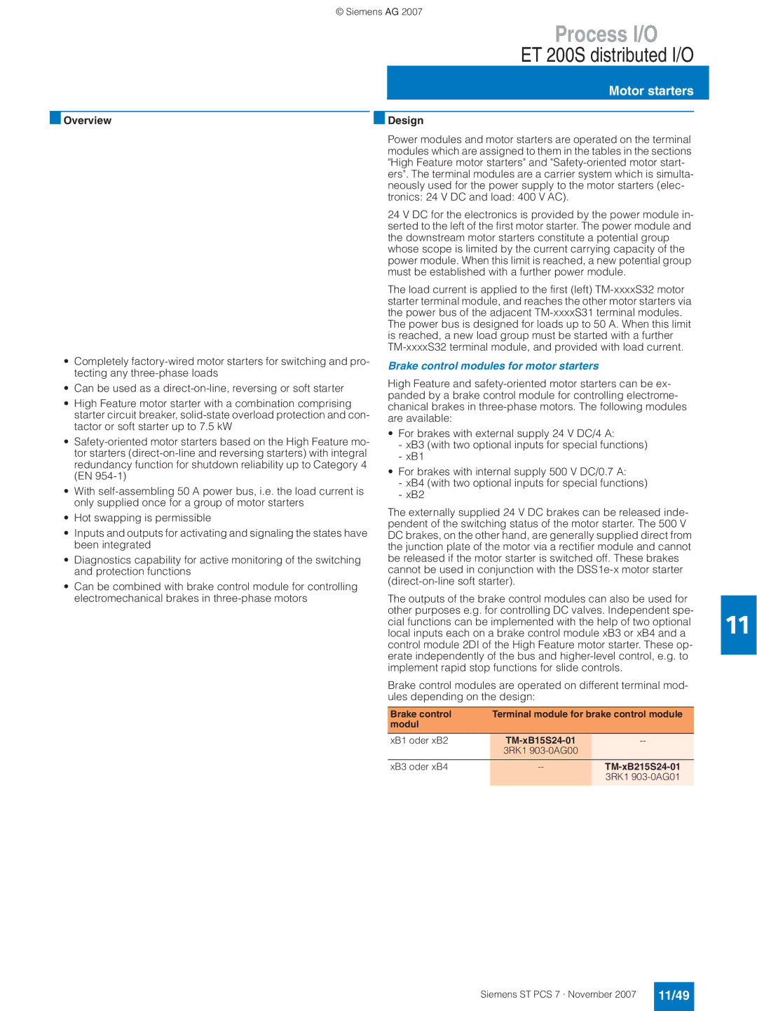
XB3 oder xB4 TM-xB215S24-01
Motor starters
11/49
Brake control modules for motor starters
11/50
High Feature motor starters
Safety-oriented motor starters
11/51
High Feature motor starters
11/52
Safety-related motor starters
PM-X
Siguard safety technology
Possible combinations of power and terminal modules
11/53
TM-X terminal module for Siguard connection module
Terminal modules for Siguard power modules
Siguard PM-D F1/F2/F3/F4/F5 power modules
11/54
PM-X Siguard
Siguard Power Modules
11/55
Siguard Terminal Modules
Expansion modules
Dezentrale Peripherie ET 200pro
11/56
Modules of an ET 200pro station
Module support
ET 200pro configuration
11/57
Mechanical stress
General technical specifications
11/58
Ambient conditions
Connection modules
Interface module IM 154-2 DP High Feature
Features of the IM 154-2 DP High Feature interface module
11/59
Digital output modules
Digital electronics modules EM 141, EM
11/60
Digital input modules
Analog input modules
Analog electronics modules EM 144, EM
11/61
Analog output modules
11/62
Further accessories
11/63
Safety-related electronics modules
Safety-related digital input module EM 8/16 F-DI PROFIsafe
11/64
Connection module
Power module PM-E
Power module
11/65
11/66
12/2
IT world
12/2
IT world
Contact partners
12/3
Integration of Simatic IT and Simatic PCS
12/4
13/2 Introduction
Simatic PCS
Migration strategy
13/2
Migration component Description
13/3
Portfolio of the migration products
Typical migration scenarios
13/4
Development of further migration products and tools
13/5
Migration spectrum
Migration Support Center
13/6
Ordering data for previous version Simatic PCS 7
Server
14/2
Single station
IL43 WXP
14/3
Client Additional and expansion components
PCS 7 Basic Package
Starter systems
14/4
Standard engineering software
Simatic PCS 7 PowerPacks for engineering software
ES software
14/5
14/6
Simatic PDM Basic
TAG options / PowerPacks
14/7
Simatic PDM Single Point
Applications
14/8
Controller optimization
Simulation with S7-PLCSIM
OS standard software for single station / server / client
OS software
14/9
OS archiving
Connectivity Pack and Client Access Licenses
Simatic Safety Matrix Viewer
14/10
Design of redundant OS single stations
14/11
OS redundancy
OS long-term archiving
PCS 7 Web Server
Simatic Batch Software
14/12
14/13
Route Control Software
14/14
Asset Management Software
Asset Engineering
Accessories
Profibus PA components
14/15
BM DP/PA
14/16
Components for hot swapping and for redundant design
Active bus modules for hot Swapping
AS 414-3 automation system comprising
Automation systems
14/17
Standard automation systems bundles
14/18
14/19
Fault-tolerant/safety-related automation systems bundles
S7 F Systems Runtime License
14/20
15/13 Simatic PCS 7 upgrades
Update Upgrade packages
15/2
Software Update Service
Software Update Service for Simatic PCS
Software Update Service for TIA products
6ES7 658-1EX00-2YL8
Simatic PCS 7 Software Update Service
Software Update Service for TIA products
15/3
Communications software/licenses for Simatic PCS 7
15/4
15/5
15/6
Simatic PDM upgrades
Simatic PDM upgrade/update service
15/7
Simatic PCS 7 upgrades V6.x to
Upgrades for engineering system
Simatic PCS 7 OS Web upgrade
Upgrades for operator system
Upgrades of OS software
Upgrade of OS long-term archiving
OS software
OS Web upgrade package
Upgrades of OS software from V6.0/V6.1 to
15/9
Simatic Batch packages for upgrading from V6.0/V6.1 to
Upgrades for Simatic Batch
15/10
Software Update Service Simatic Route Control
Upgrades for Simatic Route Control
Simatic Route Control upgrade package
Simatic Route Control upgrade packages
15/12
Upgrades for Asset Management
Simatic PCS 7 Asset upgrade
Simatic PCS 7 Asset upgrade
Engineering system
Simatic PCS 7 upgrades V4.02 to
Simatic PCS 7 upgrades V5.x/V6.0 to
15/13
15/14
Upgrades of OS software from V6.0 to
Upgrades of OS software from V5.x to
Upgrade of SFC Visualization
15/15
Simatic Route Control upgrade packages
OS software upgrade
Simatic PCS 7 upgrades V4.02 to
Engineering software upgrade for AS engineering
Engineering software upgrade for OS engineering
Appendix
16/2
Training
16/3
Siemens Contacts Worldwide
WWW
Online Services
Information and Ordering Internet and on CD-ROM
16/4
16/5
Our Services for Every Phase of Your Project
Customer Support
Small card great support
16/6
16/7
Siemens Solution Partner Automation and Power Distribution
16/8
Software Licenses
16/9
Subject index
10/24
16/10
16/11
Order no. index
16/12
6GK1 716-1CB64
16/13
16/14
16/15
For customers with a seat or registered office in Germany
Conditions of sale and delivery Export regulations
16/16
Terms and Conditions of Sale and Delivery
Automation and Drives Group A&D
Siemens AG