Model SB1016/SB1036 | O P E R A T I O N | For Machines Mfg. Since 7/09 |
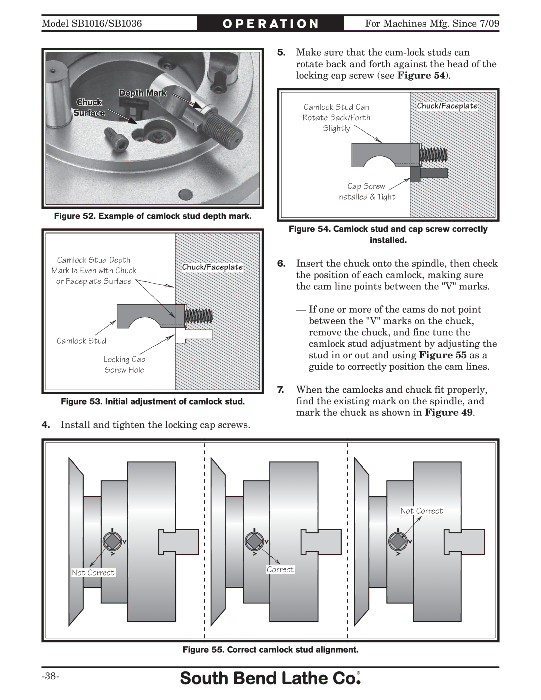
Depth Mark
Chuck
Surface
Figure 52. Example of camlock stud depth mark.
Camlock Stud Depth
Mark is Even with ChuckChuck/Faceplate or Faceplate Surface ![]()
Camlock Stud
Locking Cap
Screw Hole
Figure 53. Initial adjustment of camlock stud.
4.Install and tighten the locking cap screws.
5.Make sure that the
Camlock Stud Can | Chuck/Faceplate |
Rotate Back/Forth |
|
Slightly |
|
Cap Screw ![]()
Installed & Tight
Figure 54. Camlock stud and cap screw correctly
installed.
6.Insert the chuck onto the spindle, then check the position of each camlock, making sure the cam line points between the "V" marks.
—If one or more of the cams do not point between the "V" marks on the chuck, remove the chuck, and fine tune the camlock stud adjustment by adjusting the stud in or out and using Figure 55 as a guide to correctly position the cam lines.
7.When the camlocks and chuck fit properly, find the existing mark on the spindle, and mark the chuck as shown in Figure 49.
| Not Correct |
Not Correct | Correct |
|