Model SB1016/SB1036 | S E R V I C E | For Machines Mfg. Since 7/09 |
Brake Inspection & Replacement
The linkage geometry on this lathe is non adjustable. Before replacing the brake shoes, verify that all fasteners are tight, and all clevis pins and yokes have minimal wear. As pivot points wear, the increased slop in the linkage absorbs the usable stroke that is required for full brake application. If the brake does not stop the lathe as fast as it should, before replacing the brake shoes, verify that the linkage is not worn and is the cause of the problem.
Tools Needed: | Qty |
Another Person | 1 |
Hex Wrench 6mm | 1 |
Hex Wrench 8mm | 1 |
1 | |
Basic Caliper | 1 |
Safety Glasses | 1 |
Respirator Rated for Brake Dust | 1 |
To replace the brake shoes:
1.DISCONNECT LATHE FROM POWER!
2.Put on a respirator and eye protection to protect yourself from hazardous brake dust.
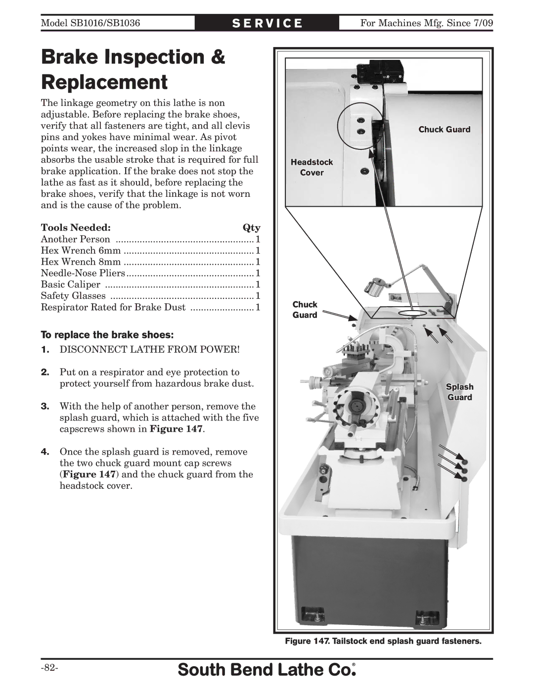
3.With the help of another person, remove the splash guard, which is attached with the five capscrews shown in Figure 147.
4.Once the splash guard is removed, remove the two chuck guard mount cap screws (Figure 147) and the chuck guard from the headstock cover.
Chuck Guard |
Headstock |
Cover |
Chuck |
Guard |
Splash |
Guard |