For Machines Mfg. Since 7/09 | P R E P A R A T I O N | Model SB1016/SB1036 |
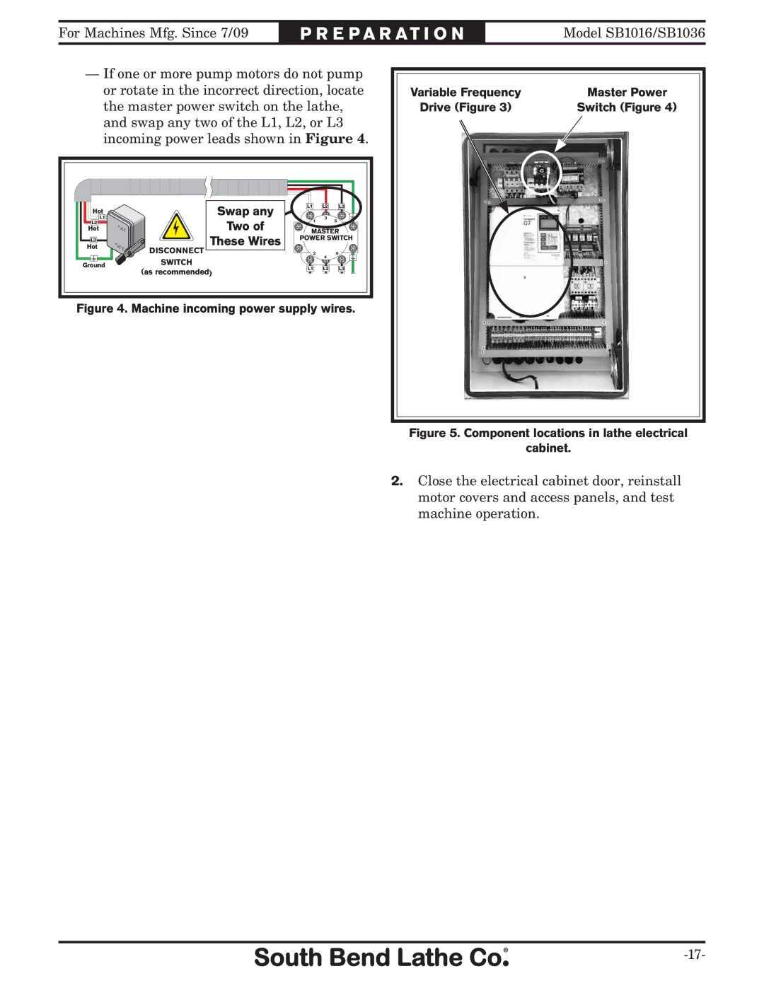
—If one or more pump motors do not pump or rotate in the incorrect direction, locate the master power switch on the lathe, and swap any two of the L1, L2, or L3 incoming power leads shown in Figure 4.
Variable Frequency | Master Power |
Drive (Figure 3) | Switch (Figure 4) |
Hot |
L1 |
L2 |
Hot |
L3 |
Hot |
Ground |
Swap any
Two of
These Wires
DISCONNECT
SWITCH
(as recommended)
L1 | L2 | L3 |
1 | 3 |
5 | |
MASTER | |
POWER SWITCH | |
2 | 6 |
| 4 |
L1 | L2 | L3 |
Figure 4. Machine incoming power supply wires.
Figure 5. Component locations in lathe electrical
cabinet.
2.Close the electrical cabinet door, reinstall motor covers and access panels, and test machine operation.
