Model SB1016/SB1036 | P R E P A R A T I O N | For Machines Mfg. Since 7/09 |
Connecting to Power
Due to the complexity required for planning, bending, and installing the conduit necessary for a
The hardwire setup for this machine must include a locking disconnect switch (see Figure 15) between the power source and the machine. This switch serves as the means to completely disconnect the machine from power to prevent electrocution accidental startup during adjustments, maintenance, or service to the machine.
|
| Locking |
|
Power Source | Disconnect Switch | Machine | |
Conduit | Conduit |
| |
Figure 15. Typical hardwire setup with a locking
disconnect switch.
Electrocution or death will occur if this procedure is attempted with live power supply wires. All wiring going to the machine must be disconnected from the power source, and the power supply shut OFF and locked out before performing this procedure.
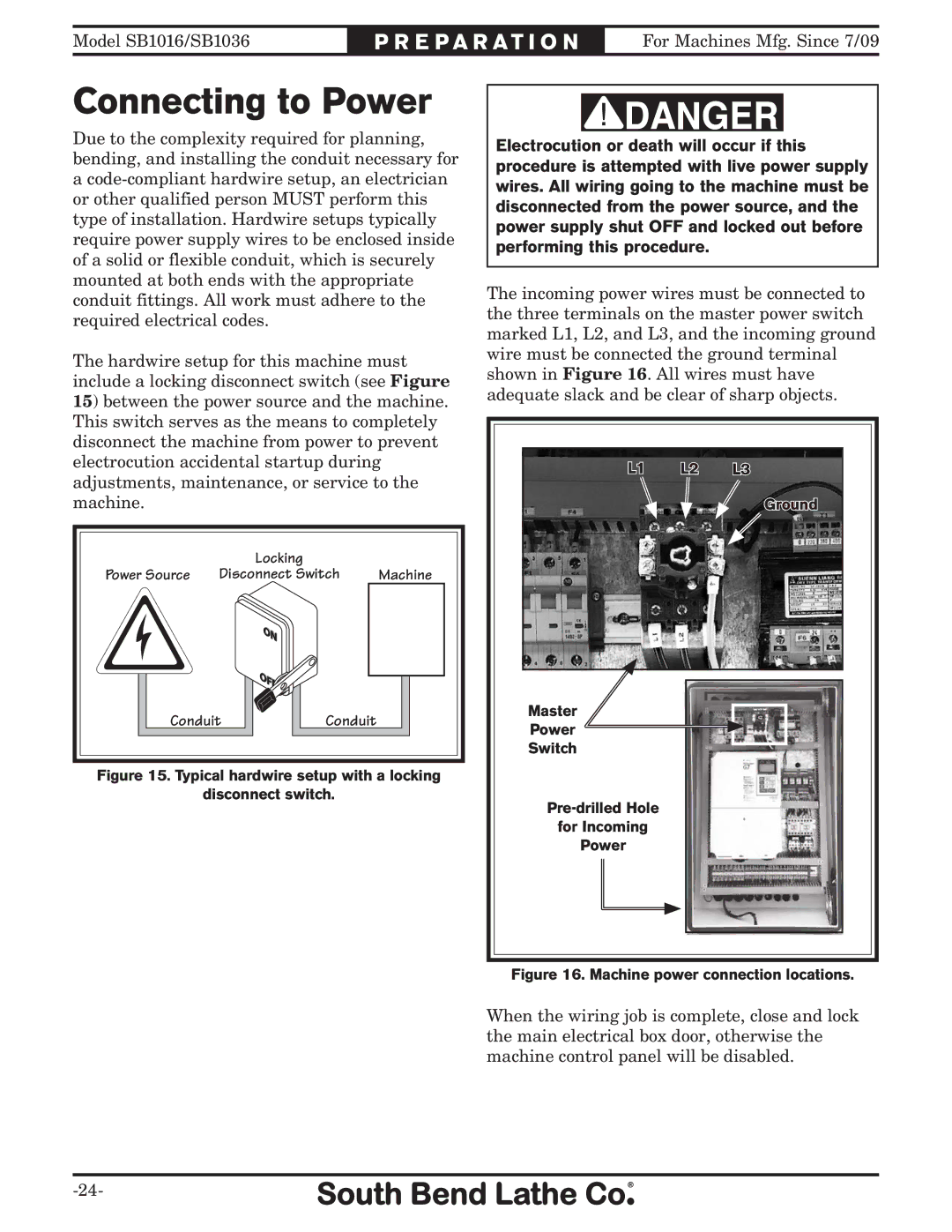
The incoming power wires must be connected to the three terminals on the master power switch marked L1, L2, and L3, and the incoming ground wire must be connected the ground terminal shown in Figure 16. All wires must have adequate slack and be clear of sharp objects.
L1 | L2 | L3 |
|
| Ground |
Master |
|
|
Power |
|
|
Switch |
|
|
|
| |
for Incoming |
|
|
Power |
|
|
Figure 16. Machine power connection locations.
When the wiring job is complete, close and lock the main electrical box door, otherwise the machine control panel will be disabled.