Model SB1016/SB1036 | M A I N T E N A N C E | For Machines Mfg. Since 7/09 |
Lubrication
Headstock
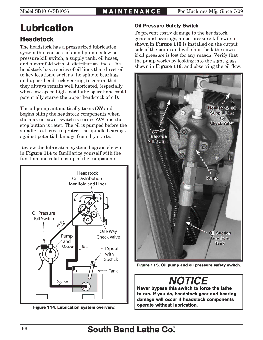
The headstock has a pressurized lubrication system that consists of an oil pump, a low oil pressure kill switch, a supply tank, oil hoses, and a manifold with oil distribution lines. The headstock has a series of oil lines that direct oil to key locations, such as the spindle bearings and upper headstock gearing, to ensure that they always remain well lubricated, (especially when
The oil pump automatically turns ON and begins oiling the headstock components when the master power switch is turned ON and the stop button is reset. The oil is pumped before the spindle is started to protect the spindle bearings against potential damage from dry starts.
Review the lubrication system diagram shown in Figure 114 to familiarize yourself with the function and relationship of the components.
Headstock |
Oil Distribution |
Manifold and Lines |
Oil Pressure Safety Switch
To prevent costly damage to the headstock gears and bearings, an oil pressure kill switch shown in Figure 115 is installed on the output side of the pump and will shut the lathe down if oil pressure is lost for any reason. Verify that the pump works by looking into the sight glass shown in Figure 116, and observing the oil flow.
Headstock Oil
Supply Line
to
Check Valve
Low Oil
Pressure
Kill Switch
Pump
Oil Pressure
Kill Switch
Pump
and
Motor
One Way
Check Valve
Return
Fill Spout
with
Dipstick
Oil Suction
Line from
Tank
Figure 115. Oil pump and oil pressure safety switch.
![]() Tank
Tank
Suction
Figure 114. Lubrication system overview.
Never bypass this switch to force the lathe to run. If you do, headstock gear and bearing damage will occur if headstock components operate without lubrication.
