Model SB1016/SB1036 | O P E R A T I O N | For Machines Mfg. Since 7/09 |
Description of Controls & Components
Refer to the following figures and descriptions to learn about the basic controls of this machine.
Main Power Control
A.Master Power Switch: The rotary switch shown in Figure 37 toggles incoming power ON/OFF to the lathe. It also prevents the electrical box door from being opened when the switch is ON. If switched to OFF, this switch is not a safe alternative to completely disconnecting the machine from power when wiring, servicing, or making repairs.
A
Figure 37. Master power switch.
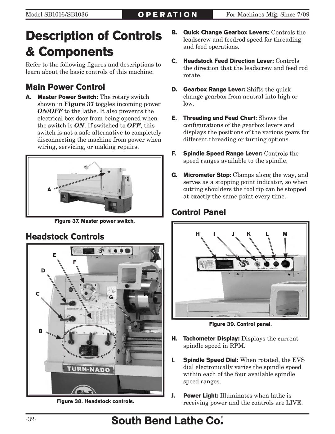
Headstock Controls
E![]()
![]()
F![]()
![]()
D
C
G
B
Figure 38. Headstock controls.
B.Quick Change Gearbox Levers: Controls the leadscrew and feedrod speed for threading and feed operations.
C.Headstock Feed Direction Lever: Controls the direction that the leadscrew and feed rod rotate.
D.Gearbox Range Lever: Shifts the quick change gearbox from neutral into high or low.
E.Threading and Feed Chart: Shows the configurations of the gearbox levers and displays the positions of the various gears for different threading or turning options.
F.Spindle Speed Range Lever: Controls the speed ranges available to the spindle.
G.Micrometer Stop: Clamps along the way, and serves as a stopping point indicator, so when cutting shoulders the tool tip can be stopped at exactly the same point every time.
Control Panel
H I | J K | L | M |
Figure 39. Control panel.
H.Tachometer Display: Displays the current spindle speed in RPM.
I.Spindle Speed Dial: When rotated, the EVS dial electronically varies the spindle speed within each of the four available spindle speed ranges.
J.Power Light: Illuminates when lathe is receiving power and the controls are LIVE.