Series B Mainframes E1300B and E1301B
User’s Manual
Page
Warranty
Limitation Of Warranty
Certification
Exclusive Remedies
Trademark Information
Safety Symbols
Printing History
Declaration of Conformity
According to ISO/IEC Guide 22 and EN
Installation and Getting Started Guide
Suggested Sequence for Using the Manuals
Agilent 75000 Series B Documentation
Manual Descriptions
Related Documents
Manual Content
About this Manual
Table of Contents
Downloading Device Drivers
Using the Mainframe
Controlling Instruments Using Gpib
System Instrument Command Reference
Specifications
Error Messages
Connecting and Configuring a Display Terminal
Sending Binary Data Over RS-232
Table of Contents
Using This Chapter
Getting Started
Mainframe Description
Optional Mainframe Memory
Mainframe Features Getting Started
Instrument Definition
Instrument Concept Getting Started
Introductory Programming Examples
Instrument Logical Addresses Instrument Secondary Addresses
Systtime 14,00,00
Systdate 1990,1,13
Getting Started
Using the Front Panel
Front Panel Features
Using Menus
Second Menu Tutorial
Using the System Instrument Menu
How to Set or Read the System Gpib Address
How to Reset the System
How to Display Logical Addresses or Instrument Information
Using the Other Instrument Menus
How to Open/Close Channels How to Scan Channels
Using the Front Panel
Reading Error Messages
Monitor Mode
Monitor Mode Display Annunciators
Trigsour Immscan @100105INIT
Executing Commands
Sourpulscoun Sourpulsper Initimm Trigsour IMM
Display Control Editing Keys
Key Descriptions
Menu Keys
Instrument Control Keys
Other Keys
Problem Problem Cause/Solution
Case of Difficulty
Instrument Menus
Using the Display Terminal Interface
System Instrument Menu
Control DTR Read
Switchbox Menu
Test
Using the Front Panel
Scanning Voltmeter Menu
Temp Tcouple
Unstrn
Agilent E1326B/E1411B 5 1/2 Digit Multimeter Standalone Menu
Agilent E1328A 4-Channel D/A Converter Menu
Agilent E1330A Quad 8-Bit Digital Input/Output Menu
Using the Front Panel
Agilent E1332A 4-Channel Counter/Totalizer Menu
Timeint CHAN1 Trigsour IMMMEAS1TINT?
Agilent E1333A 3-Channel Universal Counter Menu
CHAN2 Trigsour IMMMEAS2TINT?
Using the Front Panel
Using the Display Terminal Interface
Terminal Interface Features
Using Menus
How to Access the Utility Keys
Instrument Menu
Press f1 to Reset
How to Display Logical Addresses and Instrument Information
Is not being displayed press Utils then Selinst
How to Open/Close Channels
How to Display Module Type , Description, or Reset Module
Dispmonstat on
SYSTERR?
UTILS, RCLPREV, then Return
Executing Commands
Sourpulscoun Sourpulsper Trigsour IMM Initimm
General Key Descriptions
Menu and Menu Control Keys
Ctrl D = Select an instrument menu
Using Supported Terminals
Supported Terminals
Fields Value
Using the Display Terminal Interface
Using Other Terminals
Using the WYSE WY-30
What Not Supported Means Testing Terminals for Compatibility
Menu Name Instrument
Using a Terminal Without Menus
Instrument Names for the SI Command
Instrument Prompt then press D
Control Sequence Functions
Interface control
Using the Display Terminal Interface
Instrument Menus
System Instrument Menu
Control DTR Read
Switchbox Menu
Using the Display Terminal Interface
Scanning Voltmeter Menu
Unstrn
Agilent E1326B/E1411B 5 1/2 Digit Multimeter Standalone Menu
Agilent E1328A 4-Channel D/A Converter Menu
Agilent E1330A Quad 8-Bit Digital Input/Output Menu
Using the Display Terminal Interface
Agilent E1332A 4-Channel Counter/Totalizer Menu
Timeint CHAN1 Trigsour IMMMEAS1TINT?
Agilent E1333A 3-Channel Universal Counter Menu
CHAN2 Trigsour IMMMEAS2TINT?
Using the Display Terminal Interface
Using the Mainframe
Using the Pacer
Abort
Sourpulscoun INF
Sourpulsper 250E-3
Trigsour EXT
Systcommgpibaddr
Changing Primary Gpib Address
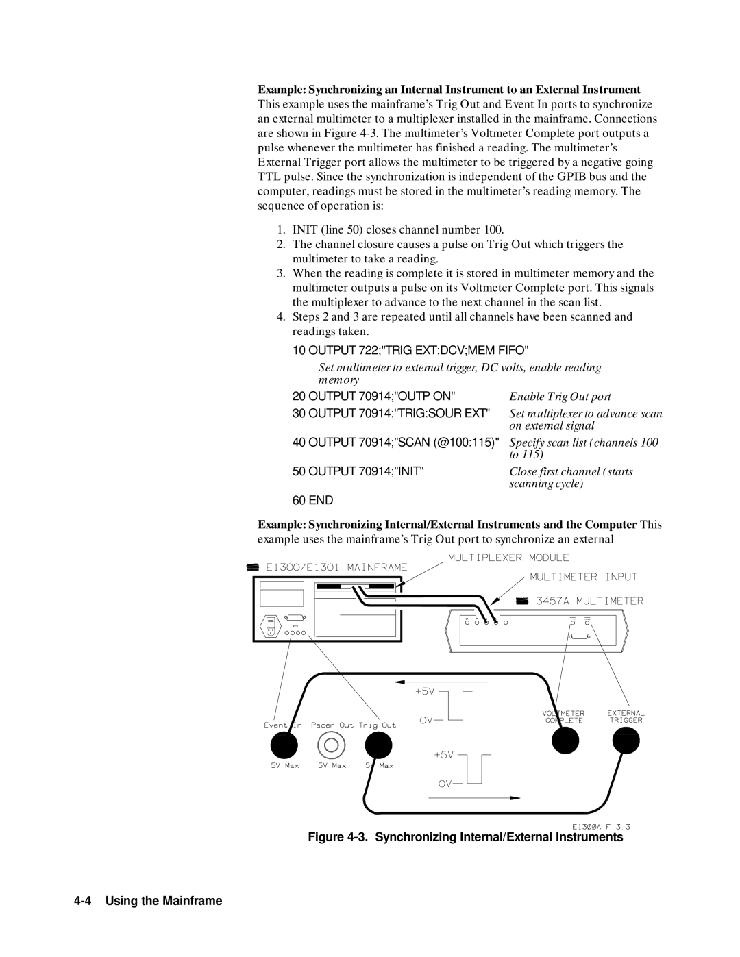
Synchronizing Internal External Instruments
Output 722TRIG Extdcvmem Fifo
Output 70914TRIGSOUR EXT
Output 722TRIG Extdcv
Output 70914OUTP on
Output 70914TRIGSOUR BUS
Output 70914INIT
Using Mainframe Data Memory
Mainframe Data Memory
Non-Volatile User Memory
Allocating a User Memory Segment
Ibasic Users
Locating the Nram
Output 70900DIAGBOOT
Real Addr,Size
Output 70900DIAGNRAMCRE
Wait
Using DOWNload UPload? to Access Data
Output 70900 Using Diagdown ,8D,,# 232,16W Addr+ 96,Words
Output 70900 Using Diagdown ,8D,,# 232,32B Addr+ 64,Bytes
Output 70900 Using Diagdown ,8D,,# 264,64A Addr,Chars$
Chars$= 1234567890123456789012345678901234567890
Downloading Device Drivers
Downloading Device Drivers
About this Chapter
Driver and Documentation Usage Downloading Device Drivers
Memory Configuration
Positioning of Allocatable RAM
Download Program Configuration
Editing the Configuration File
Downloading Device Drivers
Downloading Drivers in MS-DOS Systems
Downloading Drivers in Gpib Systems with
Progexec ’MSI ,700,1’
Downloading Drivers in Gpib Systems with Basic
Checking Driver Status
Downloading Multiple Drivers
Reboot the system
Manually Downloading a Driverdown manual
Preparing Memory for Manual Downloading
Defined the Driver RAM
Transmission Format
Diagcomm Stor
SYSTCOMMSERPACETHRSTOP? MAX
Systcommserpacethrstar
Systcommserpacexon
Asserted. This acts to pace the System Instrument output
Cat filename device file
Page
Downloading Device Drivers
Programming Hints
Controlling Instruments Using Gpib
Controlling Instruments Using Gpib
Status System Structure
Status Byte Register
Status Byte Register
Bit Decimal Number
Reading the Status Byte Register
Status Byte Register
Print P
SRE?
Standard Event Status Register
Unmasking Standard Event Status Bits
Standard Event Status Register
ESE
ESE?
ESR?
DIAGnosticINTerruptRESPonse?
STATusOPERationENABle event
STATusOPERationENABle?
Operation Status Group Condition Register
Enable Intr
Output 70900 DIAGINTSETUP5 on Output 70900 Diagintact on
CLS
Output 70900 Statoperenab
SUB Intrresp = SPOLL70900
Clearing Status
Interrupting an External Computer
Example Interrupting when an Error Occurs
Synchronizing an External Computer Instruments
Output 70909SOURVOLT1 5*OPC?
Enter 70909A
Enter 70903A
END While
Controlling Instruments Using Gpib
System Instrument Command Reference
Command Types
Common Command Format
System Instrument Command Reference
DIAGINTSETupn? and SYSTCOMMSERialnBAUD?
DIAGINTSETUP2?, DIAGINTPRI2 5, SYSTCOMMSER1BAUD
ROUTeSCANMODE?
SOURce PULSe COUNt COUNt? PERiod PERiod?
# non-zero digit digits data bytes
Indefinite Length Block
# 0 data bytes NL END
Rstoutp on Trigsour HOLD*TRG
Scpi Command
Reference
ABORt
Abort
Subsystem Syntax DIAGnostic
DIAGnostic
DIAGnostic
DIAGnosticBOOTCOLD
Related Commands Diagbootwarm
Re-booting the System Instrument cold
Diagbootcold
DIAGnostic Bootwarm
Diagbootwarm
Diagcommser Ibas Diagbootwarm
COMMunicate SERial0OWNer
COMMunicate
SERial0OWNer?
SERialnSTORe
DIAGCOMMSER?
Parameters DIAGnostic DOWNloadCHECked MADDress
DIAGnosticCHECkedDOWNloadMADDress address , data writes
Parameter Range Default Name Type
DOWNloadCHECked MADDress
DIAGnosticDOWNloadCHECked MADDress
Data Value Check Bits
1FC0016 + Laddr * 64 + registernumber
Parameters DIAGnostic DOWNloadCHECked SADDress
DOWNloadCHECked SADDress
DIAGnosticDOWNloadCHECked SADDress
Parameters DIAGnostic DOWNload MADDress
DOWNload MADDress
DIAGnosticDOWNloadSADDress
1FC00016 + Laddr * 64 + registernumber
DIAGnostic DRAMAVAilable?
Example Downloading Data to a Single Address Location
Diagdownsadd # H1FCA20,#
DIAGDRAMAVA?
DIAGnosticDRAMCREate
DIAGnosticDRAMCREate size numdrivers creates a non-volatile
DRAMCREate
Example Allocate a 15 Kbyte non-volatile Driver Ram segment
Parameters DIAGnostic DRIVerLOAD driverblock
DRIVerLOAD
Parameters Comments Example
Diagdrivload
DIAGDRIVLISTROM?
DIAGnosticDRIVer LISTtype?
Diagdrivlist ?
DIAGnostic INTerruptACTivate
Read with the DIAGnosticINTerruptRESPonse? command
Example Enable an Interrupt Acknowledgement on Line
INTerruptACTivate
DIAGnosticINTerruptSETupn?
Example Setup and wait for VXI interrupt response on line
DIAGINTSETUP2 on
Example Determine interrupt setup for line
DIAGnostic INTerruptPRIorityn
INTerruptPRIorityn
INTerruptPRIorityn?
DIAGINTPRI2
DIAGINTRESP?
DIAGnosticINTerruptRESPonse?
DIAGINTSETUP2 on
DIAGnostic NRAMADDRess?
DIAGnosticNRAMCREate size
NRAMCREate
DIAGNRAMADDR?
DIAGnosticNRAMCREate?
DIAGNRAMCREate?
DIAGPEEK? 16252928,8
Enter statement
DIAGnostic Poke
DIAGnosticPOKE address , width , data writes data number
Diagpoke 16252928,8,255
DIAGRDISADDR?
DIAGnosticRDISkCREate
RDISkCREate
Diagrdiscre
DIAGRDISCRE?
DIAGnostic UPLoadMADDress?
DIAGnosticUPLoadMADDress? address , bytecount Returns
Example Upload data stored on non-volatile User RAM
Output DIAGUPL? value of ADD ,1024
DIAGnosticUPloadSADDress?
DIAGnosticUPLoadSADDress? address , bytecount Returns
Example Upload data stored in non-volatile User RAM
Output DIAGUPLSADD? # H1FCA20,1024
Related Commands ABORt, TRIGger
INITiate
INITiate IMMediate
Init
SOURce
PULSeCOUNt
PULSeCOUNt?
Sourpulscoun 1E3
SOURPULSPER?
PULSePERiod
SOURce PULSePERiod
Example Reading the contents of the condition register
STATus
STATus OPERation CONDition?
STATOPERCOND?
STATus OPERationENABle?
Related Commands STATOPERENABle?
STATus PRESet
Example Presetting the Enable Register
Example Reading the Event Register
STATOPEREVEN?
SYSTem
SYSTem BEEPerIMMediate
Example Sound the Beeper
Systbeepimm
SYSTemCOMMunicate GPIBADDRess
Example Set the Gpib port’s primary address
Systcommgpibaddr
SYSTCOMMGPIBADDR?
SYSTCOMMSER0CONTDTR on
SYSTem COMMunicate SERialn CONTrol DTR Example
Parameters Comments
SYSTCOMMSER0CONTDTR?
Example Checking the setting of DTR control
SYSTemCOMMunicate SERialn CONTrol DTR?
SYSTCOMMSER0BAUD
Example SYSTem COMMunicate SERialn CONTrol RTS?
Example COMMunicate SERialn RECeive BAUD?
SYSTemCOMMunicate SERialn RECeive Bits
Example COMMunicate SERialn RECeive BITS?
SYSTCOMMSER0BITS
SYSTCOMMSER0BITS?
Pace PROTocol
Pace PROTocol?
SYSTem COMMunicate SERialn RECeive Pace PROTocol
SYSTCOMMSER0PACEPROT XON
SYSTemCOMMunicate SERialn RECeive Pace THReshold STARt
SYSTemCOMMunicateSERial n RECeive PACETHResholdSTARt
SYSTCOMMSER0PACETHRSTAR
Example Return current start threshold
SYSTemCOMMunicateSERial n RECeive PACETHResholdSTOP
SYSTCOMMSER0PACETHRSTOP
Example Return current stop threshold
SYSTCOMMSER0PACETHRSTOP?query for threshold
PARity CHECk?
SERialn RECeive
PARity Type
SYSTCOMMSER0PARCHEC on
SYSTem COMMunicate SERialn RECeive PARity Type
SYSTCOMMSER0PAR ODD
PARity TYPE?
SBITs
SYSTemCOMMunicate SERialn RECeive PARity TYPE?
SYSTCOMMSER0PAR?
SYSTemCOMMunicateSERialnRECeiveSBITs? MIN MAX returns
SYSTCOMMSER0TRANAUTO on
Example Is Auto on or OFF?
SYSTCOMMSER0TRANAUTO?
SYSTCOMMSER0TRANPACEPROT?
SYSTemCOMMunicate SERialnTRANsmit Pace PROTocol
SYSTCOMMSER0TRANPACEPROT XON
Example Setting the system Date
SYSTem DATE?
Systdate 1991,09,08
DATE? SYSTemDATE? MIN MAX,MIN MAX,MIN MAX returns
SYSTemTIME
Systtime 14,30,20
SYSTTIME?
Input values of hour,min,sec
DELay
TRIGger DELay
Trigdelay .75 S
TRIGger
TRIGgerIMMediate
Triggering the Pacer
Trig
Discrete NEGative None
RST Condition Trigsour IMM
TRIGger SOURce?
Parameter Value Source of Trigger
CONFigure DLADdress?
VXICONFigure DLADdress?
Example Determining the device addresses within the system
VXICONFDLAD?
VXI CONFigureDLISt?
N1, n2, n3, n4, n5, n6, c1, c2, c3, c4, c5, s1, s2, s3, s4
N1 Device’s Logical Address. a number from 0 to
N6 Slot 0 Logical Address. a number from 0 to
VXICONFigure DNUMber? Parameters
Example Querying the device list for the System Instrument
Example Determining the number of devices within the system
VXICONFDNUM?
CONFigure HIERarchy?
VXI CONFigure HIERarchy?
VXICONFigure HIERarchyALL?
CONFigure HIERarchyALL?
CONFigure INFormation?
VXICONFINF?
Example Query information on logical address
Vxisel
CONFigure INFormationALL?
CONFigure LADDress?
VXICONFigure INFormationALL?
Related Commands VXICONFNUMB?
Numericvalue or the following optional words
Example Read from one of a device’s configuration registers
VXI REGisterREAD?
Related Commands Vxisel
VXIREGisterWRITe
SELect
VXI SELect
VXIWRITe
Vxiwrit 8,24,# H4200
Common Command Reference
DMC namestring Commandblock
Output 70900*DMC ’LIST’,# 0VXICONFDLIS?
Output 70900*ESR?
Output 70900*ESE?
Enter 70900A
Example Get the ID fields from the system and print them
Print A$
Output 70900*ESE
Output 70900*PSC
Output 70900*SRE
Output 70900*SRE
Output 70900*SRE?
Print a
Gpib Message
Go To Local GTL
Group Execute Trigger GET
Interface Clear IFC
Device Clear DCL or Selected Device Clear SDC
Local Lockout LLO
Serial Poll Spoll
Remote
Remote
10 P= Spoll
Command Quick Reference
Scpi Commands Quick Reference
Command Description
Command Quick Reference
Nram
BAUD? MIN MAX
VXI
Synchronization
Instrument Status
Macros
Command Quick Reference
Specifications
Mainframe Specifications
Specifications A-1
Trigger Input Non-volatile added memory storage lifetime
Weight
Power
Operating temperature
Storage temperature
Switchbox Configuration
Table A-1. Switchbox SCPI-1990.0 Confirmed Commands
Table A-2. Switchbox Non-SCPI Commands
Specifications A-3
Table A-3. Multimeter SCPI-1990.0 Confirmed Commands
Table A-4. Multimeter Scpi Approved not confirmed Commands
Table A-5. Multimeter Non-SCPI Commands
Specifications A-5
Table A-6. Agilent E1332A SCPI-1990.0 Confirmed Commands
Table A-7. Agilent E1332A Non-SCPI Commands
Specifications A-7
Table A-8. Agilent E1333A SCPI-1990.0 Confirmed Commands
Table A-9. Agilent E1333A Non-SCPI Commands
Table A-11. Agilent E1328A Non-SCPI Commands
Commands
Table A-10. Agilent E1328A SCPI-1990.0 Confirmed Commands
Specifications A-9
Table A-12. Agilent E1330A SCPI-1990.0 Confirmed Commands
Table A-13. Agilent E1330A Non-SCPI Commands
Table A-15. System Instrument SCPI-1991.0 Confirmed Commands
Table A-16. System Instrument SCPI-1992.0 Approved Commands
Specifications A-11
Table A-17. System Instrument Non-SCPI Commands
Table A-18. Common Commands SCPI-1990.0 Confirmed
Specifications
Error Messages
Reading an Instrument’s Error Queue
Error number , error description string
Error Messages B-1
Error Number Error Type
Error Types
Table B-1. Negative Error Numbers
Error Messages B-3
Table B-2. Error Messages and Causes
Error Messages and Causes Code
2110
Start-up Error Messages
Table B-3. Start-up Error Messages and Warnings
Start-Up Error Messages and Warnings Code Cause
Error Messages B-5
Error Messages
Connecting and Configuring a Display Terminal
Connecting a Terminal to the Mainframe
Connecting and Configuring a Display Terminal C-1
Overview
To Connect to Gpib
Connecting and Configuring a Display Terminal C-3
Configuring a Terminal for the Mainframe
Configuring the Terminal
Configuring the Mainframe with Menus
How to Use the Serial Interface Menus
Connecting and Configuring a Display Terminal C-5
How to Store the Serial Interface Configuration
Sending Binary Data Over RS-232
Formatting Binary Data for RS-232 Transmission
Bit #
Sending Binary Data Over RS-232 D-1
Setting Up the Mainframe
Sending Binary Data Over RS-232
Table D-1. Correction Codes for RS-232 Transmission
Sending Binary Data Over RS-232
Sending Binary Data Over RS-232 D-3
Sending Binary Data Over RS-232
Index
Index-1
Index-2
Systdate
Index-3
Index-4
Index-5
Index-6
Index-7
VXIREGREAD?
Index-8