Replaceable Parts
Assembly and Disassembly Guidelines
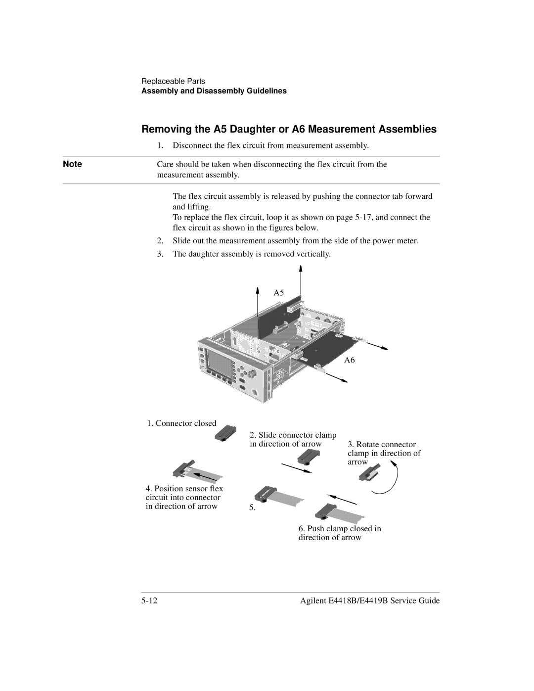
Removing the A5 Daughter or A6 Measurement Assemblies
| 1. | Disconnect the flex circuit from measurement assembly. | ||||||||
|
|
|
|
|
|
|
|
|
| |
Note | Care should be taken when disconnecting the flex circuit from the | |||||||||
| measurement assembly. | |||||||||
|
|
|
|
|
|
|
|
|
|
|
|
| The flex circuit assembly is released by pushing the connector tab forward | ||||||||
|
| and lifting. | ||||||||
|
| To replace the flex circuit, loop it as shown on page | ||||||||
|
| flex circuit as shown in the figures below. | ||||||||
| 2. | Slide out the measurement assembly from the side of the power meter. | ||||||||
| 3. | The daughter assembly is removed vertically. | ||||||||
|
|
|
|
| A5 |
|
|
|
|
|
|
|
|
|
|
|
|
|
|
| |
|
|
|
|
|
|
|
|
|
| |
|
|
|
|
|
|
|
|
|
| |
|
|
|
|
|
|
|
|
|
| |
|
|
|
|
|
|
|
|
|
|
|
|
|
|
|
|
|
|
|
|
|
|
|
|
|
|
|
|
|
|
|
|
|
|
|
|
|
|
|
|
|
|
|
|
A6
1.Connector closed
4.Position sensor flex circuit into connector in direction of arrow
2.Slide connector clamp in direction of arrow
5.
3.Rotate connector clamp in direction of arrow ![]()
6.Push clamp closed in direction of arrow
Agilent E4418B/E4419B Service Guide |