Replaceable Parts
Assembly and Disassembly Guidelines
Removing the A2 Processor Assembly
1.Remove the A5 daughter and A6 measurement assemblies as described on page
2.Move the A2 plastic support bracket to its forward position using the two side levers, unclip the
3.Disconnect the following cables from the A2 processor assembly:
n
n
n
power reference
fan connector
power supply connector
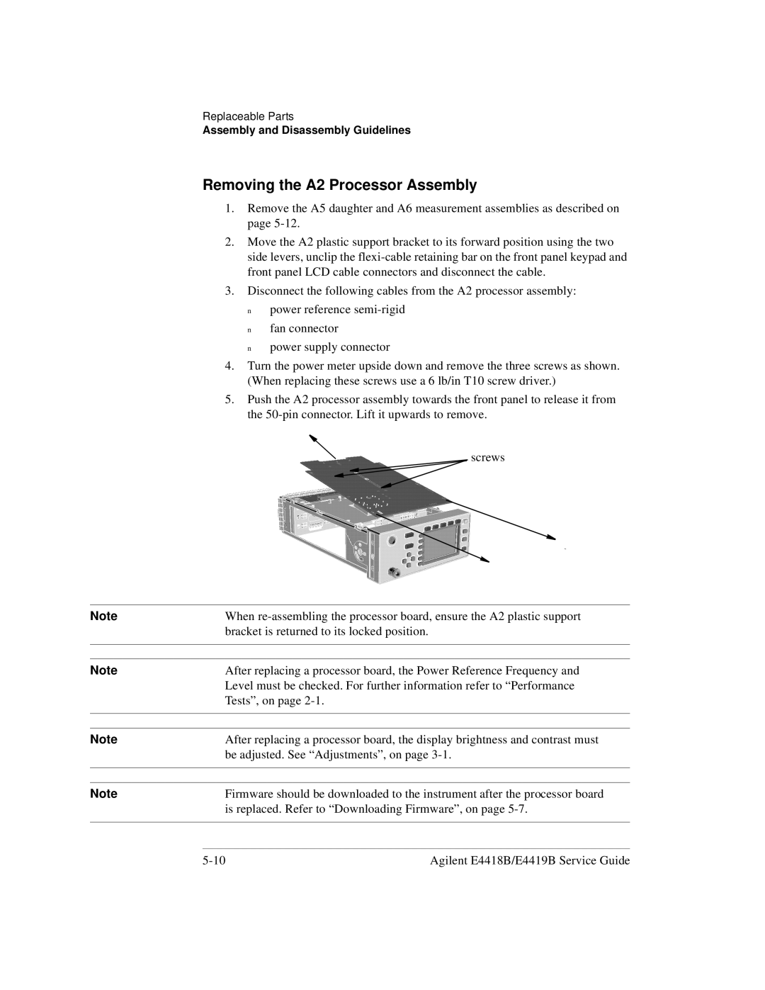
4.Turn the power meter upside down and remove the three screws as shown. (When replacing these screws use a 6 lb/in T10 screw driver.)
5.Push the A2 processor assembly towards the front panel to release it from the
screws |
Note | When |
| bracket is returned to its locked position. |
|
|
|
|
Note | After replacing a processor board, the Power Reference Frequency and |
| Level must be checked. For further information refer to “Performance |
| Tests”, on page |
|
|
|
|
Note | After replacing a processor board, the display brightness and contrast must |
| be adjusted. See “Adjustments”, on page |
|
|
|
|
Note | Firmware should be downloaded to the instrument after the processor board |
| is replaced. Refer to “Downloading Firmware”, on page |
|
|
Agilent E4418B/E4419B Service Guide |