Performance Tests
Power Reference Level Test
Equipment
•Test power meter: Agilent 432A.
•Thermistor mount: Agilent 478A option H75 or H76.
•Digital voltmeter (DVM): Agilent 3458A.
Test Setup |
| ||
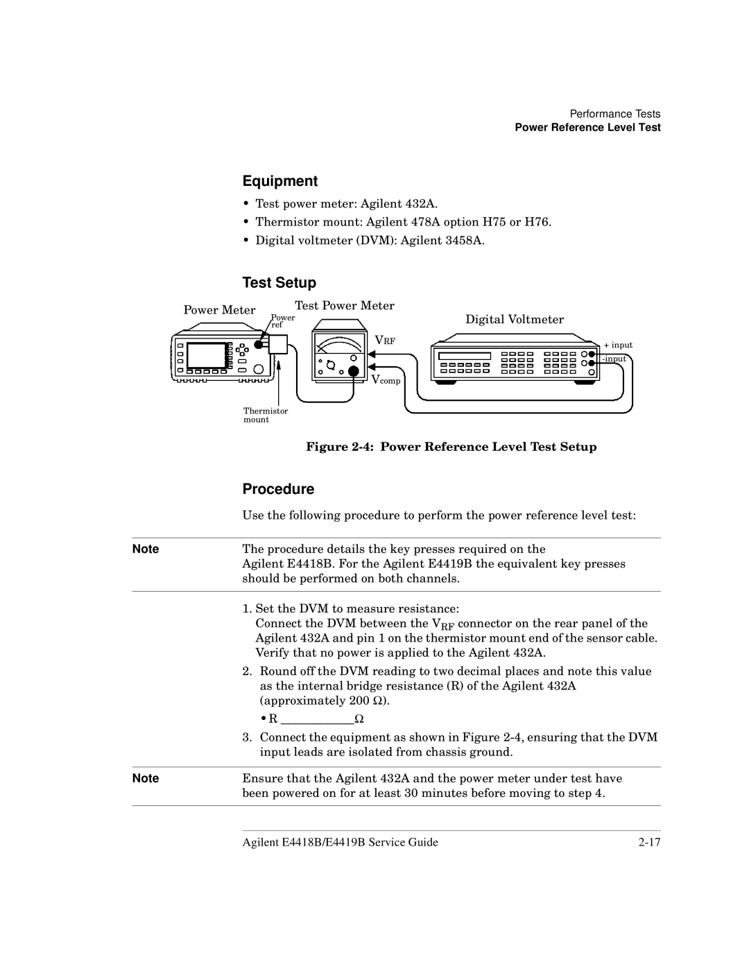
Power Meter | Test Power Meter | Digital Voltmeter | |
Power | |||
| |||
| ref |
| |
| VRF | + input | |
|
| ||
|
| ||
| Vcomp |
| |
Thermistor mount
Figure 2-4: Power Reference Level Test Setup
Procedure
Use the following procedure to perform the power reference level test:
Note | The procedure details the key presses required on the |
| Agilent E4418B. For the Agilent E4419B the equivalent key presses |
| should be performed on both channels. |
|
|
1.Set the DVM to measure resistance:
Connect the DVM between the VRF connector on the rear panel of the Agilent 432A and pin 1 on the thermistor mount end of the sensor cable. Verify that no power is applied to the Agilent 432A.
2.Round off the DVM reading to two decimal places and note this value
as the internal bridge resistance (R) of the Agilent 432A (approximately 200 Ω).
•R ____________Ω
3.Connect the equipment as shown in Figure
Note | Ensure that the Agilent 432A and the power meter under test have |
| been powered on for at least 30 minutes before moving to step 4. |
|
|
Agilent E4418B/E4419B Service Guide |