Adjustments
Power Reference Oscillator Level Adjustment
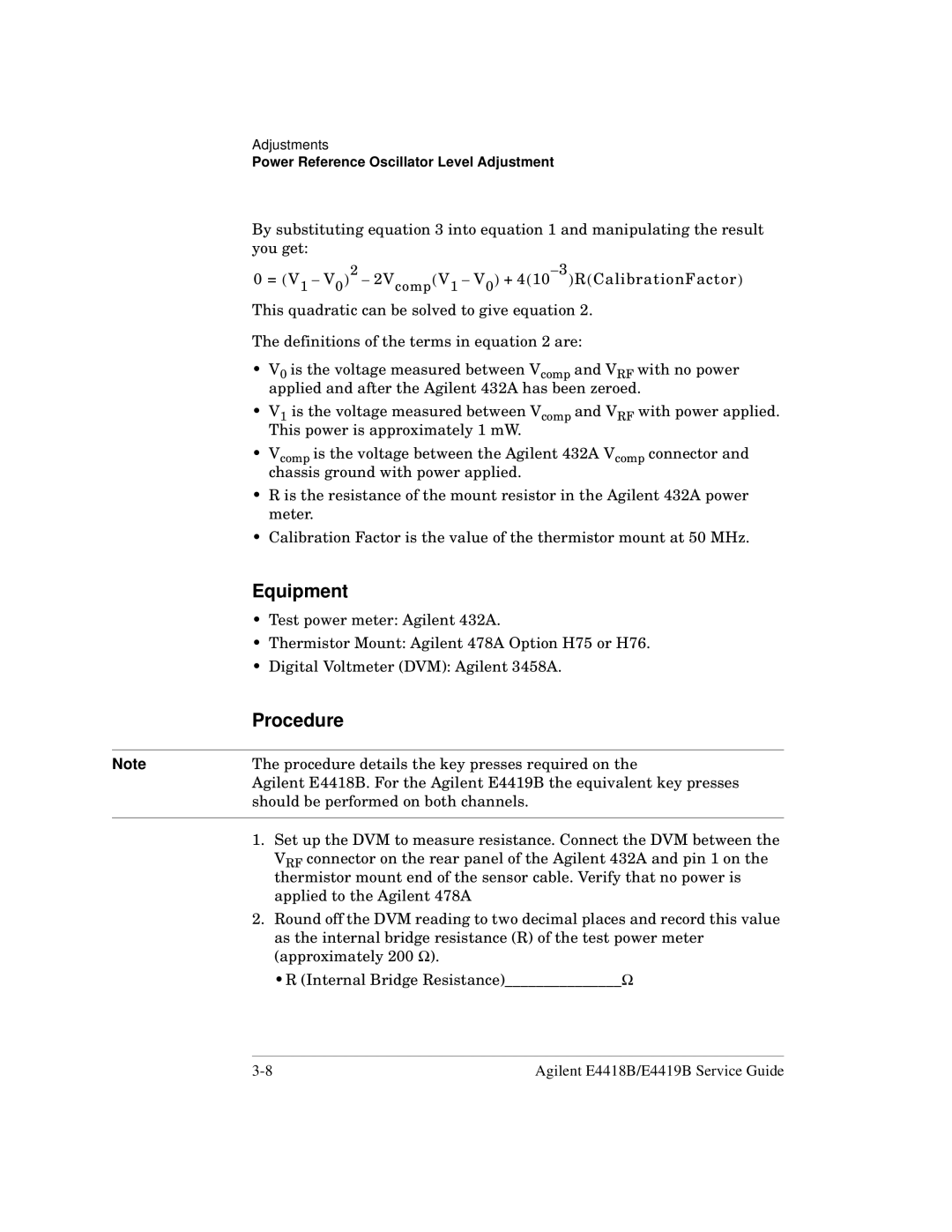
By substituting equation 3 into equation 1 and manipulating the result you get:
0 = (V1 – V0)2 – 2Vcomp(V1 – V0) +
This quadratic can be solved to give equation 2.
The definitions of the terms in equation 2 are:
•V0 is the voltage measured between Vcomp and VRF with no power applied and after the Agilent 432A has been zeroed.
•V1 is the voltage measured between Vcomp and VRF with power applied. This power is approximately 1 mW.
•Vcomp is the voltage between the Agilent 432A Vcomp connector and chassis ground with power applied.
•R is the resistance of the mount resistor in the Agilent 432A power meter.
•Calibration Factor is the value of the thermistor mount at 50 MHz.
Equipment
• Test power meter: Agilent 432A.
• Thermistor Mount: Agilent 478A Option H75 or H76.
• Digital Voltmeter (DVM): Agilent 3458A.
| Procedure |
|
|
Note | The procedure details the key presses required on the |
| Agilent E4418B. For the Agilent E4419B the equivalent key presses |
| should be performed on both channels. |
|
|
| 1. Set up the DVM to measure resistance. Connect the DVM between the |
| VRF connector on the rear panel of the Agilent 432A and pin 1 on the |
| thermistor mount end of the sensor cable. Verify that no power is |
| applied to the Agilent 478A |
| 2. Round off the DVM reading to two decimal places and record this value |
| as the internal bridge resistance (R) of the test power meter |
| (approximately 200 Ω). |
| •R (Internal Bridge Resistance)_______________Ω |
Agilent E4418B/E4419B Service Guide |
