AI2524 Router
User’s Manual
Applied Innovation Inc
August Reference 2524UM
FCC Warning
AI2524 Router User’s Manual Copyright Notice
Electrostatic Discharge Warning
Contents
Edit Command Lines that Wra
Setup Command Facility Task List
Introduction System Configuration Dialog
Using the System Configuration Dialog
AI2524 Protocol Configuration Steps
Manually Loading System Images
AI2524 OSI/CLNP Configuration Steps
TOC-5
Configure Miscellaneous Tarp PDU Information
Serial Interface Configuration Steps 10-1
AI2524 Sync PPP Configuration Steps 11-1
Configure the Synchronous Serial Interfaces 10-1
TOC-7
13-1
13-18
T1 Interface Configuration Steps 14-1
13-13
13-47
System Error Messages 18-1
Basic Configuration 16-1
Command References 17-1
Debug Command Reference 19-1
Documentation Overview
Introduction
Introduction
This chapter describes how to enable PPP en
This chapter describes how to configure th
This chapter describes how to configure syn
Configuration tasks
Includes the release notes for this version
Documentation for AISwitch products includes
Related Documentation
This appendix defines acronyms used in this
Contact Information
Arguments
Avaccess switchname
Variable
Cat filename
Ls file directory
Text could cause damage or unre
Liable results
AI2524 Router Card User’s Manual
Introduction
Four Wires 56K CSU/DSU
AI2524 Overview
IN-1 Serial Cable Interface
Scalability
Software Features Functions
Remote Access and Protocol Translation
Reliable, Adaptive Routing
AI2524 Overview
1Remote Access Functionality
AI2524 Overview Management and Security
Specifications
Software
Supported Media
IP Routing Protocols
WAN protocols
Network protocols
Frame Relay High-Level Data Link Control Hdlc PPP 25 a
Connections
External Connection Requirements
AI2524 Router Card User’s Manual
Configuration Overview
Introduction Boot Router for First Time
Configure the Router
Using Configuration Mode
Prompt changes to the privileged Exec enable prompt
Show Configuration
Results of the show running-config and show startup
Use Configuration Builder
Save the Configuration
Configuration Overviews
Use the Command Interpreter
Configuration Overview
Store the Configuration on the AI198 Card
Configuration Storage and Hot Swap
Always Modify the Configuration Using Menu
Use the Web Browser Interface
Command Line Interface
Understanding the User Interface
End a Session User Interface Task List
Quit
Understanding the User Interface
AI2524 Router Card User’s Manual
Command Mode Access Method Prompt Exit Method
User Exec Mode Commands
Key#
Privileged Exec Mode Commands
Bug
ROM Monitor Mode Commands
Copy running-config startup-config command be
You can also enter ROM monitor mode by entering the reload
Fore issuing the reload command
Configuring from terminal, memory, or network terminal?
Maximum interval before running lowest priority process
Interface Configuration Mode Commands
Level 2 parameters Link Access Procedure, Balanced
Subinterface Configuration Mode Commands
Router Configuration Mode
IPX-Router Configuration Mode
Response Time Reporter Configuration Mode
Key Chain Configuration Mode
Key Chain Key Configuration Mode
Access-List Configuration Mode
Help Command Command Format
Context-Sensitive Help
Understanding the User Interface Get Word Help
Get Command Syntax Help
Get Help for Abbreviated Commands
Examples
Enter the configure command followed by a space and a ques
Tion
Check Command Syntax
Tional options
Now you can complete the command entry
Tax for entering the time
Size number-of
History Commands Command Format
Lines
User Exec mode, reenable
Editing Commands Command Format
Terminal editing
Ing
Revert to the editing mode of previous
Terminal no edit
Releases
August
Web Browser Interface Task List
Enable the Web Browser Interface
Web Browser Interface
Use Compatible Hardware and Software
AI2524 Router Card User’s Manual Access Your Routers Home
1Example of a Home
August 2524UM
Enter Commands Using the URL Window
Http//example/exec/show/configuration
Using AutoInstall
Using AutoInstall
Preparing for AutoInstall
Enter the copy running-config startup-config com- mand
AutoInstall Requirements
Ip helper
Use a DOS-Based Tftp Server
How AutoInstall Works
Acquire the New Routers IP Address
1Using Slarp to Acquire the New Routers IP Address
2Use Bootp or Rarp to Acquire the New Routers IP Address
Resolve the IP Address to the Host Name
AI2524 Router Card User’s Manual
Download the New Routers Host Configuration File
Please Wait. AutoInstall being attempted
Use an HDLC-Encapsulated Serial Interface Connection
Perform AutoInstall Procedure
Modify the Existing Routers Configuration
Ip address address mask
Clock rate bps
To exit configuration mode, press Ctrl-Z
Use an Ethernet, Token Ring, or Fddi Interface Connection
Interface ethernet tokenring fddi interface-number
Interface serial
Copy running-config startup-config
Use a Frame Relay-Encapsulated Serial Interface Connection
Encapsulation frame-relay
Set Up the Tftp Server
Clock rate bps1
Existing router might need to forward Tftp requests
Same network segment as the new router. When you
Modified the existing routers configuration, you specified
Response packets if the Tftp server is not on
Set Up the Bootp or Rarp Server
Connect the New Router to the Network
Exec command to verify connectivity. If an incorrect
Verify that the existing and new routers and/or access
Command to save configuration changes. Use the ping
Configuration file is downloaded, the new router will load
Setup Command Facility Task List
Use Setup for Configuration Changes
Use Setup after First-Time Startup
Command. Also, verify the logical port assignments using
If you use setup to modify a configuration because you
Physical connections using the show version
Show running-config command to ensure that
Setup Facility, for more information
Configuration register, the router enters the streamlined
Setup command facility. Refer to Use the Streamlined
NVRAM, or if the ignore Nvram bit is set in th
AI2524 Router Card User’s Manual
Using AutoInstall
AI2524 Router Card User’s Manual
Using AutoInstall
AI2524 Router Card User’s Manual
Use the Streamlined Setup Facility
Server and your configuration has insufficient IP
Message Configuring interface IP parameters for
Netbooting only appears if you are booting over a network
Information
Using the System Configuration Dialog
Introduction System Configuration Dialog
Messages displayed vary, depending on the Cisco IOS
Default parameters for the console port are
Baud, 8 data bits, no parity, and 2 stop bits
Are for reference only and may not exactly reflect
BRI0
Enter the enable and virtual terminal passwords
Enter an enable secret password
Configure the appropriate protocols for your router
Refer to this table for Isdn switch types
Country Isdn Switch Type Description
AI2524 Router Card User’s Manual
Manually Loading System Images
Configuration that you want to modify
Image Configuration File Load Task List
Organization of tasks assumes you have a minimal
Copy System Images from a Network Server to Flash Memory
Retrieve System Images Configuration Files
Retrieve System Images and Configuration File Task List
Device
Be sure there is enough available space before copying a
File to Flash memory. Use the show flash command
Appear, where xxxx/xxxx is the number of bytes read
Compare the size of the file you want to copy to
OK 1906676/4194240 bytes Verifying via checksum
Enter y and confirm the erasure, the erase routine begins
If you enter n after the Erase flash before
Writing? prompt, the copy process continues. If you
Be sure you have enough Flash memory space before
Copy Configuration Files from a Network Server to Router
When prompted, enter the server IP address or domain name
Change the Buffer Size for Loading Configuration Files
Copy tftp running-config startup-config
Boot buffersize bytes
Display System Image and Configuration Information
Verify the Image in Flash Memory
Show version
Show startup-config
Show flh-log
Verify flash
This example illustrates how to use this command
Reexecute the Configuration Commands in Startup
Clear the Configuration Information
Configure memory
General Startup Task List
Enter Configuration Mode and Select a Configuration Source
These methods are described in these sections
Configure the Cisco IOS software from the Terminal
Host network
Configure the Cisco IOS software from Memory
Configure the Cisco IOS software from the Network
Ip-address
How the Router Uses the Boot Field
Copy a Configuration File Directly to the Startup
Modify the Configuration Register Boot Field
Copy tftp startup-config
Setting the Boot Field
Perform the Boot Field Modification Tasks
Config-register value
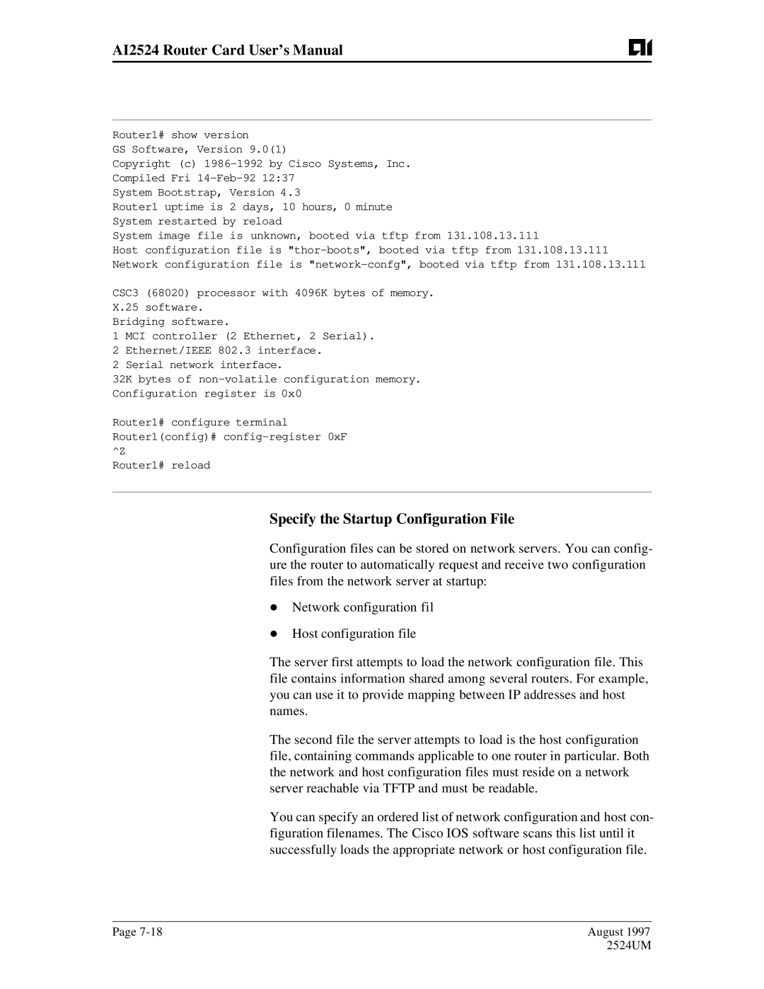
Specify the Startup Configuration File
Download the Host Configuration File
Specify the Startup Configuration File Task List
Download the Network Configuration File
Boot network tftp filename ip-address
Boot host tftp filename ip-address
Copy System Images from Flash Memory to a Network Server
Store System Images Configuration Files
Store System Images and Configuration Files Task List
Show flash all
Configure terminal command with
ROM
Copy Configuration Files from the Router to a Network Server
Copy running-config startup-config tftp
Startup Task List
Partition Flash Memory Using Dual Flash Bank
Tasks
Systems that Support Dual Flash Bank
Flash Load Helper versus Dual Flash Bank
Understanding Relocatable Images
Dual Flash Bank Configuration Task List
Exec mode, download a file into a Flash partition
Helper software in boot ROMs
Partition flash partitions size1 size2
Copy tftp flash
Boot flash flash flash filename
Method of Downloading Result of Booting from Flash
Boot flash flash flash partition- number
Boot flash flash flash partition- numberfilename
Boot system flash flash flash partition-numberfilename
Boot system flash flash flash partition-number
Boot system flash flash flash filename
Tftp-server flash filename
AI2524 Router Card User’s Manual
Flash Load Helper Configuration Task List
Download a File Using Flash Load Helper
Enter the name of the file you want to copy
Enter the name of the destination file
System configuration has been modified. Save? confirm
Manually Load a System Image from ROM Monitor
Manually Boot from Flash
Monitor Flash Load Helper
Manually Boot from a Network File
Use the System Image Instead of Reloading
Manually Boot from ROM
Continue
AI2524 Router Card User’s Manual
AI2524 Protocol Configuration Steps
Configuration Steps
Enable Ospf
Configure Ospf Interface Parameters
Enable Ospf MD5 authentication
Configure Ospf over Different Physical Networks
Ip ospf authentication-key key
Ip ospf dead-interval seconds
Area area-idauthentication message-digest
Configure Ospf for Nonbroadcast Networks
Configure Ospf Area Parameters
Neighbor ip-addresspriority number poll-interval seconds
Define an area to be a stub area
Configure Ospf Not So Stubby Area Nssa
Area area-iddefault-cost cost
Area area-idstub no-summary
Area area-id range address mask
Configure Route Summarization between Ospf Areas
Implementation Considerations
Summary-address address mask
Configure Lookup of DNS Names
AI2524 Protocol Configuration Steps Create Virtual Links
Generate a Default Route
Ip ospf name-lookup
Interface loopback
Disable Default Ospf Metric Calculation Based on Bandwidth
Configure Ospf on Simplex Ethernet Interfaces
No ospf auto-cost-determination
Configure Ospf over On-Demand Circuits
Timers spf spf-delay spf-holdtime
AI2524 Router Card User’s Manual Network Illustration
To take advantage of the Ospf stub area support, default
Routing must be used in the stub area
Igrp Updates
Igrp Configuration Task List
Router igrp process number
Allow Point-to-Point Updates for Igrp
Define Unequal-Cost Load Balancing
Neighbor ip-address
Adjust the Igrp Metric Weights
Control Traffic Distribution
Because of the complexity of this task, we recommend that
Disable Holddown
Enforce a Maximum Network Diameter
You only perform it with guidance from an experienced
No validate-update-source
1Interior, System, and Exterior Routes
Allow Point-to-Point Updates for RIP
RIP Configuration Task List
Enable RIP
Router rip
Version 1
Specify a RIP Version
Ip rip send version 1
AI2524 Router Card User’s Manual Enable RIP Authentication
Disable Route Summarization
Disable the Validation of Source IP Addresses
No validate-update-source ion
No default-information in out
Route-map map-tagpermit deny sequence-number
Configuration Task List
AI2524 OSI/CLNP Configuration Steps
AI2524 OSI/CLNP Configuration Steps
Understand Addresses
1NSAP Address Fields
2Sample Domain and Area Addresses
ISO Igrp Nsap Address
3ISO Igrp Nsap Addressing Structure IS-IS Nsap Address
4IS-IS Nsap Addressing Structure Addressing Rules
AI2524 Router Card User’s Manual Addressing Examples
Routing Table Example
Entry Nsap Address Next-Hop NET Prefix
Datagram Destination Nsap Table Entry Address Number Used
Dynamic Routing
Intermediate Systems is and End Systems ES
Static Routing
Routing Decisions
Enable ISO Igrp
Configure ISO Igrp Dynamic Routing
Router iso-igrp tag
Clns router iso-igrp tag level
Example Dynamic Routing within the Same Area
Define a tag castor for the routing process
Example Dynamic Routing in More Than One Area
6CLNS Dynamic Routing within Two Areas
Define a tag orion for the routing process
Example Dynamic Routing in Overlapping Areas
Define a tag cancer for the routing process
Net 47.0004.004d.0004.0000.0C00.0506.00
7CLNS Dynamic Interdomain R outing
Router Chicago
Specify iso-igrp routing with the tag a
Define a tag B for the routing process
Specify iso-igrp routing with the tag B
Adjust ISO Igrp Metrics
Configure ISO Igrp Parameters
Router Detroit
Enable or Disable Split Horizon
Adjust ISO Igrp Timers
Metric weights qos k1 k2 k3 k4 k5
Configure IS-IS Dynamic Routing
Enable IS-IS
Enable IS-IS routing on ethernet
Examples IS-IS Routing Configuration
Configure the NET for the process in area 47.0004.004d.0001
Level1 and Level2 Routing
Configure a level 2 adjacency only for interface serial
OSI Configuration
Enable IS-IS routing on serial
Level2 Routing Only
Specify a cost of 5 for the level-1 routes
ISO Clns Dynamic Route Redistribution
Router is in areas 47.0004.004d.0001 and 47.0004.004d.0011
Establish a level-1 adjacency
Assign Multiple Area Addresses to IS-IS Areas
Redistribute IS-IS routing information
This example illustrates using a name for a NET
Examples NETs Configuration
These are examples of configuring NETs for both ISO Igrp
This example illustrates specifying a NET
Example Router in Two Areas
IS-IS Multihoming
This example illustrates specifying a single NET
001F in this example net is the hex value for area
This example net is the hex value for area
Configure IS-IS Parameters
Ignore-lsp-errors
Configure IS-IS Authentication Passwords
Ignore IS-IS Link-State Packet LSP Errors
Specify Router-Lev elSupport
Log-adjacency-changes
Log Adjacency State Changes
Change IS-IS LSP MTU Size
Lsp-mtu size
Isis metric default-metriclevel-1 level-2
Adjust IS-IS Link-State Metrics
Set the Advertised Hello Interval and Hello Multiplier
Isis hello-multiplier multiplier level-1 level-2
Set the Advertised Csnp Interval
Isis hello-interval seconds level-1 level-2
Isis csnp-interval seconds level-1 level-2
Specify Designated Router Election
Set the Retransmission Interval
Specify the Interface Circuit Type
Isis password password level-1 level-2
Configure Clns Static Routing
Enable Static Routes
Clns net net-address name
Examples Basic Static Routing
Configure this network entity title for the routing process
Example
9Static Routing
Create a static route for the interface
Assign a static address for the router
Example Static Intradomain Routing
Specify end system for static routing
Specify iso-igrp routing using the specified tag sales
Enable ISO Igrp routing of Clns packets
Configure net chicago, as shown in steps
Define the name detroit to be used in place of this Nsap
Example Static InterdomainRo uting
Set the interface up as a DTE with X.25 encapsulation
Router a
Specify iso-igrp routing using the specified tag orion
Define the tag bar to be used in place of Router Bs Nsap
Router B
Map Nsap Addresses to Media Addresses
Configure Variations of the Static Route
Clns route default nsap-prefix type number
Clns route nsap-prefix type number snpa- address
Clns es-neighbor nsap snpa
For more information, refer to Configure Clns over WANs
Clns is-neighbor nsap snpa
Specify Shortcut Nsap Addresses
Configure Miscellaneous Features
Clns host name nsap
Create Packet-Forwarding Filters and Establish Adjacencies
Clns filter-set sname permit deny template
Redistribute Routing Information
Clns access-group name in out
Examples Clns Filter
Apply a filter expression to Isis adjacencies
Router isis tag
Redistribute iso-igrp tag route-map map- tag
Redistribute isis tag route-map map-tag
Route-map map-tagpermit deny sequence- number
Match clns route-source name name...name
Match clns address name name...name
Match clns next-hop name name...name
Match clns interface type number type number...type number
Examples Route Map
Specify Preferred Routes
Configure ES-IS Hello Packet Parameters
Distance value clns
Clns holding-time seconds
Clns esct-time seconds
Configure Clns over WANs
Example ISO Clns over
Assume the host is a DTE and encapsulates
Define the X.121 address of 31101 for serial
Enhance ISO
Configure this side as a DCE
Configure the Nsap of Router a and accept reverse charges
Performance
Disable Fast Switching Through the Cache
Disable Checksums
AI2524 Router Card User’s Manual Specify the MTU Size
Cisco IOS software when the router is acting as an is
Transmit Error Protocol Data Units ERPDUs
Control Redirect Protocol Data Units RDPDUs
Clns want-erpdu
Example Performance Parameters
Clns packet-lifetime seconds
Send IS/ES hellos every 45 seconds
Monitor Maintain the ISO Clns Network
Which-route nsap-address clns-name
Configure Tarp on ISO Clns
PDU
Enable Tarp and Configure a Tarp TID
Tarp enable
Configure Multiple Nsap Addresses
AI2524 OSI/CLNP Configuration Steps Disable Tarp Caching
Disable Tarp PDU Origination and Propagation
Configure Static Tarp Adjacency and Blacklist Adjacency
Tarp route-static nsap
Determine TIDs and NSAPs
Tarp blacklist-adjacency nsap
AI2524 OSI/CLNP Configuration Steps Configure Tarp Timers
Monitor and Maintain the Tarp Protocol
Tarp protocol hex-digit
Examples Tarp Configuration
Basic Tarp Configuration Example
Complex Tarp Configuration Example
13Sample Tarp Configuration
Introduction Configure Synchronous Serial Interfaces
Serial Interface Configuration Steps
Serial Interface Configuration Steps
AI2524 Router Card User’s Manual
Introduction Configuration Overview
AI2524 Sync PPP Configuration Steps
AI2524 Sync PPP Configuration Steps
AI2524 Router Card User’s Manual PPP Configuration Task List
Enable PPP Encapsulation Enable Chap or PAP Authentication
Encapsulation ppp
Disable PPP on the line
If you use a list-name that has not been configured
With the aaa authentication ppp command, you
Username name password secret
Ppp use-tacacs single-line Aaa authentication ppp
Example Chap with an Encrypted Password
Configure Router
Configure Router zzz
Enable Link Quality Monitoring LQM
Ppp quality percentage
Autodetect encapsulation encapsulation-type
Peer Address Allocation
Configure IP Address Pooling
Enable compression
Ppp compress predictor stac
Precedence Rules
Interfaces Affected
Define the Global Default Mechanism
Choose the IP Address Assignment Method
Define Dhcp as the Global Default Mechanism
Ip dhcp-server ip-address name
Peer default ip address ip-address
Configure Per-Interface IP Address Assignment
Peer default ip address pool poolname
Ip local pool poolname low-ip-address high-ip-address
Interface async number
Configure PPP Callback
No interface available when attempting the return call, it
Line is busy, no retry occurs. If the callback server has
Example PPP Callback Client
Ppp authentication chap pap
Dialer hold-queue packets timeout seconds
Dialer in-band no-parity odd-parity
Dialer hold-queue number timeout seconds
Dialer callback-secure
Example PPP Callback Server
On the PPP callback server, the dialer enable-timeout
Functions as the timer for returning calls to the callback
Client
If entered on a dialer or async-group interface, this
Configure PPP Half-Bridging
Command affects all member interfaces
An interface cannot function as both a half-bridge and a
Half-bridge per Ethernet subnetwork
You must enter the ppp bridge command either when
Cisco IOS software supports no more than one PPP
Interface is shut down or before you provide a protocol
Configure Multilink PPP
Configure Multilink PPP on Asynchronous Interfaces
Enable Multilink PPP. ppp multilink
Configure Multilink PPP on a Single Isdn BRI Interface
Dialer load-threshold load inbound outbound either
Enable Multilink PPP on the dialer rotary group
Configure the Isdn interface to call the remote site
Ppp authentication pap
Dialer load-threshold load
Configure Multilink PPP on Multiple Isdn BRI Interfaces
Dialer idle-timeout seconds
Dialer-group group-number
Ppp authentication chap
Dialer rotary-group group-number
AI2524 Router Card User’s Manual
August 2524UM
Understand Virtual Private Dial-up Networks
Configure Virtual Private Dial-up Networks
This implementation of Vpdn supports PPP dial-up only
Sessions for which individual dial-in calls have arrived on
MMP feature uses Vpdn to connect multiple PPP
Reliability for the setup and shutdown of Multilink PPP
Different stack group members. Vpdn provides speed
Interface virtual-template number
Ip local pool default ip-address
Ip unnumbered ethernet
Vpdn incoming remote-namelocal-namevirtual-template number
Example Network Access Server Servicing Multiple Domains
Vpdn outgoing domain-name local-name ip ip- address
Gateway2-Domain2
Gateway1-Domain1
Example NAS Servicing Multiple Domains to the Same Gateway
Gateway
Example Using TACACS+ for Forwarding from the NAS
TACACS+ Server
Vty-async
Monitor Maintain MLP MMP, and Vpdn Virtual Interfaces
Show vpdn
Configuration Task List
AI2524 X.25 Configuration Steps
Often it is used
Configure Interface
Set the X.25 Mode
Consultative Committee for International Telegraph
ITU-T carries out the functions of the former
Telephone Ccitt
Example Virtual Circuit Ranges
Virtual circuit range limits when the interface is up are
Held until the X.25 protocol restarts the packet service
Because the X.25 protocol requires the DTE and DCE to
Set the Packet Numbering Modulo
When the interface is up are held until the X.25 protocol
Restarts the packet service
Set the X.121 Address
Set Default Window Sizes
Set Default Packet Sizes
Example Typical X.25 Configuration
Interface serial Ip address 172.25.9.1 Encapsulation
Configure the X.25 Level 3 Timers
Configure Additional Interface
Parameters
Configure X.25 Addresses
Understand Normal X.25 Addressing
Configure an Interface Alias Address
Understand X.25 Subaddresses
Suppress or Replace the Calling Address
Establish a Default Virtual Circuit Protocol
Suppress the Called Address
Configure an Datagram Transport
No x25 linkrestart
Configure Subinterfaces
Understand Point-to-Point and Multipoint Subinterfaces
Create and Configure X.25 Subinterfaces
Example Point-to-Point Subinterface Configuration
Map Protocol Addresses to X.121 Addresses
Protocol Protocol Identifier
Understand Protocol Identification
AI2524
0x01
IP datagrams can be identified with a 1-byte identification
Default, although the Snap encoding can be configured
Map Datagram Addresses to X.25 Hosts
0xCC or a 6-byte identification 0x80 followed by
You can map an X.121 address to as many as nine
Once in the command line
Protocol addresses, but each protocol can be mapped only
Establish an Encapsulation PVC
Configure PAD Access
Multiprotocol maps, especially those configured to carr
Loads, requiring a larger hold queue, larger window sizes
Configuration for Router
Configuration for Router Y
If you specify both ip and compressedtcp in the same
Configure X.25 Bridging
X25 map compressedtcp command, they must both
Specify the same IP address
Configure Additional Datagram Transport Features
Configure X.25 Payload Compression
X25 idle minutes
Configure the Encapsulation Virtual Circuit Idle Time
Specify an idle time for clearing a maps SVCs
X25 th delay-count
Configure the Ignore Destination Time
X25 hold-vc-timer minutes
Establish the Packet Acknowledgment Policy
X25 facility windowsize in-sizeout-sizeor
X25 facility cug group-number
X25 facility packetsize in-sizeout-sizeor
Set reverse charging
Select throughput class negotiation
Select transit delay
Allow reverse charging acceptance
Set the AI2524 standard network user identification
X25 hold-queue queue-size
Define the Virtual Circuit Packet Hold Queue Size
Restrict Map Usage
Restrict outgoing calls from a map
Configure X.25 Routing
Example X.25 Route Address Pattern Matching
Enable X.25 Routing
X25 routing use-tcp-if-defs
Configure a Local X.25 Route
3X.25 Route Address Pattern Matching
AI2524 Router Card User’s Manual Example X.25 Routing
Pattern ip ip-addressxot-source type
Configure XOT Remote X.25 Route
X25 route #position x121-address cud
Number
X25 pvc number1 interface type number pvc
Example PVC Switching on the Same Router
Service tcp-keepalives-in Service tcp-keepalives-out
Number2 option
Configure an XOT Remote PVC
4X.25 Tunneling Connection
Example Remote PVC Tunneling
5Local Switching and Remote Tunneling PVCs
Configure Additional Routing Features
Configure XOT to Use Interface Default Flow Control Values
Substitute Addresses in a Local X.25 Route
Configure XOT Alternate Destinations
Translate the X.25 destination address for local switching
Address substitution is not available for XOT routes
Configure Cmns Routing
Enable Cmns on an Interface
X25 map cmns nsap mac-address
Example Cmns Configured for X.121 and MAC Addresses
X25 map cmns nsap x121-address
Example Cmns Switched over a PDN
6Example Network Topology for Switching Cmns over a PDN
Example Cmns Switched over Leased Lines
AI2524 Router Card User’s Manual
Create X.29 Access Lists
Apply an Access List to a Line
X29 access-list access-list-numberdeny
AI2524 Router Card User’s Manual Create an Access List
Example X.29 Access List
Permit x121-address
Example X.29 Profile Script
Access-classaccess-list-number
X29 profile name parameter value parametervalue
Configure a Lapb Datagram Transport
Example Typical Lapb Configuration
Modify Lapb Protocol Parameters
Siz e
Task Lapb Values Command Default Parameter
Modulus
Seconds
AI2524 X.25 Configuration Steps
Configure Lapb Priority and Custom Queuing
Configure Transparent Bridging over Multiprotocol Lapb
Monitor and Maintain Lapb
AI2524 Router Card User’s Manual
Same IP subnet address space. In this case, the subnet is
All four serial ports configured for the two routers
Following configuration example must be assigned to
172.20.170.0
Example Booting from a Network Server over
Configuration for Router B
AI2524 X.25 Configuration Steps
AI2524 Router Card User’s Manual
Introduction Frame Relay Hardware Configuration
AI2524 Frame Relay Configuration Steps
AI2524 Frame Relay Configuration Steps
Frame Relay Configuration Task List
Enable Frame Relay Encapsulation on an Interface
Configure Dynamic Mapping
Configure Static Mapping
Frame-relay map clns dlci broadcast
Two Routers in Static Mode Example
Examples Static Address Mapping
Define a Dlci used to connect to a bridge
Allow LMI Autosense to Operate
IPX Routing Example
LMI Autosense Process
Copy running-config destination
Configuring LMI Autosense
Explicitly Configure the LMI
Set the LMI Type
Keepalive number
Set the LMI Polling and Timer Intervals
Set the LMI Keepalive Interval
Frame-relay lmi-n392dce threshold
Configure Frame Relay Switched Virtual Circuits
Configure SVCs on a Physical Interface
Configure SVCs on a Subinterface optional
Example SVCs on an Interface
Map-group group-name
Define a map class and its QOS settings
Example SVCs on a Subinterface
Specify destination protocol addresses for a map-class
Map-class frame-relay map-class-name
Configure a Map Class
Define another map class and its QOS settings
Frame-relay priority-group list-number
Associate the Map Class with Static Protocol Address Maps
Configure a Map Group with E.164 or X.121 Addresses
Configure Lapf Parameters
X121 destination-address
Manipulation of Layer 2 parameters is not recommended
Configure Frame Relay Traffic Shaping
Specification for Lapf
If you do not know well the resulting functional change
Frame-relay traffic-shaping
Enable Frame Relay Traffic Shaping on the Interface
Specify a Traffic-Shaping Map Class for the Interface
Frame-relay class map-class-name
Define Priority Queue Lists for the Map Class
Define Access Lists
Frame-relay custom-queue-list number
Example Frame Relay Traffic Shaping
AI2524 Frame Relay Configuration Steps
Customize Frame Relay for Your Network
Configure Frame Relay Subinterfaces
Understand Frame Relay Subinterfaces
With IP, reducing the addressing burden that might
Point-to-point subinterfaces can be unnumbered for us
Otherwise result
Define Frame Relay Subinterfaces
Examples Basic Subinterface
Define Subinterface Addressing
Frame-relay interface-dlci dlci option
Frame-relay interface-dlci dlci
Frame-relay map bridge dlci ietf broadcast
Example IPX Routes over Frame Relay Subinterfaces
Configure Transparent Bridging for Frame Relay
All PVCs configured on a subinterface belong to the same
Bridge group
Example Unnumbered IP over a Point-to-Point Subinterface
Interface serial number.subinterface-numberpoint-to-point
Point-to-Multipoint Interfaces
Interface serial number.subinterface-numbermultipoint
Configure a Backup Interface for a Subinterface
Configure the subinterface
Configure Frame Relay Switching
Backup delay enable-delay disable-delay
Specify the Static Route
Enable Frame Relay Switching
Frame-relay switching
Frame-relay intf-type dce dte nni
4PVC Switching Configuration
5Frame Relay DCE Configuration
AI2524 Router Card User’s Manual
Configuration for Router C
6Hybrid DTE/DCE PVC Switching
Configuration for Router B
7Frame Relay Switch over IP Tunnel
Configuration for Router D
If you change from a point-to-point subinterface to a
Number. Frame Relay Inverse ARP will be on by default
Create a Broadcast Queue for an Interface
Multipoint subinterface, then change the subinterface
Packet-rate
Configure Payload Compression
Configure TCP/IP Header Compression
Frame-relay map protocol protocol-address dlci
However, if you configure the interface with Ietf
If you configure an interface with Cisco encapsulation
Inherit the compression characteristics of the interface
Encapsulation, the interface cannot be configured for
Configure an Interface for TCP/IP Header Compression
Cisco
Enter these commands
Disable TCP/IP Header Compression
This first example, the initial configuration is
Example Disabling Inherited TCP/IP Header Compression
Example Disabling Explicit TCP/IP Header Compression
Configure Dlci Priority Levels
Frame-relay de-group group-number dlci
Priority levels, the last Dlci specified in the command
Access server in fact, they are independent of the devices
Priority queues. However, if you enable queuing and use
Dlci priority levels provide a way to define multiple
Clear frame-relay-inarp
Example Configuration Providing Backward Compatibility
Monitor Frame Relay Connections
Show frame-relay lmi type number
Example Booting from a Network Server over Frame Relay
Interoperability is provided by Ietf encapsulation
Frame-relay map ip 131.108.126.200 101 broadcast
AI2524 Router Card User’s Manual
Enable Data Inversion Before Transmission
T1 Interface Configuration Steps
T1 Interface Configuration Steps
Fractional T1
Choose either D4 Super Frame sf or Extended Super
Specify the Frame Type of a FT/T1 Line
Specify the CSU Line Build Out
Frame esf
Service-module t1 linecode ami b8zs
Enable Remote Alarms
Service-module t1 lbo none
Service-module t1 remote-alarm-enable
Loopback command without specifying any keywords
Enable Loopcodes that Initiate Remote Loopbacks
By entering the service-module t1 remote
You enable the standard-loopup codes, which use a 1-in-5
T1 Interface Configuration Steps Specify Timeslots
Service-module t1 timeslots range all speed 56
AI2524 Router Card User’s Manual
Service-module 56k clock source line internal
56/64-kbps Switched and Digital Data Services DDS Interface
Introduction Set the Clock Source
Service-module 56k clock rate line-speed
Set the Network Line Speed
Change between DDS and Switched Dial-Up Modes
Enable Scrambled Data Coding
Service-module 56k data-coding scrambled
Enable Acceptance of a Remote Loopback Request
Service-module 56k switched-carrier att other sprint
Configuring
Basic Configuration
Network
Configuring the Router
Booting the Router for the First Time
Basic Configuration Using Configuration Mode
Using AutoInstall
Enter the copy running-config startup-config command
AI2524 Router Card User’s Manual
Press Enter or enter yes to begin the configuration process
Brio
Country Isdn Switch Type Description
Configuring the Ethernet or Token Ring Interfaces
Configuring Synchronous Serial Interfaces
Isdn
Enter the configure terminal command
Configuring Switched
Enter the exit command to exit configuration mode
Return to user Exec mode
Enter configuration mode
Set the network type to switched
Assign an IP address to the serial port on the module
Set the network type to DDS
Configuring Fractional T1/T1
Module
Specifying the Boot Method
Basic Configuration
Checking Configuration Settings
Command References
Command References
Command References
AI2524 Router Card User’s Manual
System Error Messages
System Error Messages
System Error Messages
AI2524 Router Card User’s Manual
Debug Command Reference
Debug Command Reference
Debug Command Reference
AI2524 Router Card User’s Manual
Appendix a Release Notes
Appendix a Release Notes
A-2 August 2524UM
August
AISwitch Release Notes
Applied Innovation, Inc
FCC Warning
Router card
New Features
August 1997AI2524 Router Card, Version 1.00 Release Notes
Manual, document number 2524UM
ISDN/BRI Inferface
AI2524 Router Card, Version 1.00 Release Notes August
August AI2524 Router Card, Version 1.00 Release Notes
Enter the exit command to exit configuration mode
Appendix B Acronyms
Acronym Definition
CIP
DTE
Lapb
Ncia
ROM
UDP
B-8 August 2524UM