Page
Important Safety Instructions
Safety guidelines
Safety Compliance
Welcome to the AV8 Preamp Processor
Contents
Audio
Installation
Positioning the Unit
Video
Cables
Speaker Installation
Digital Output
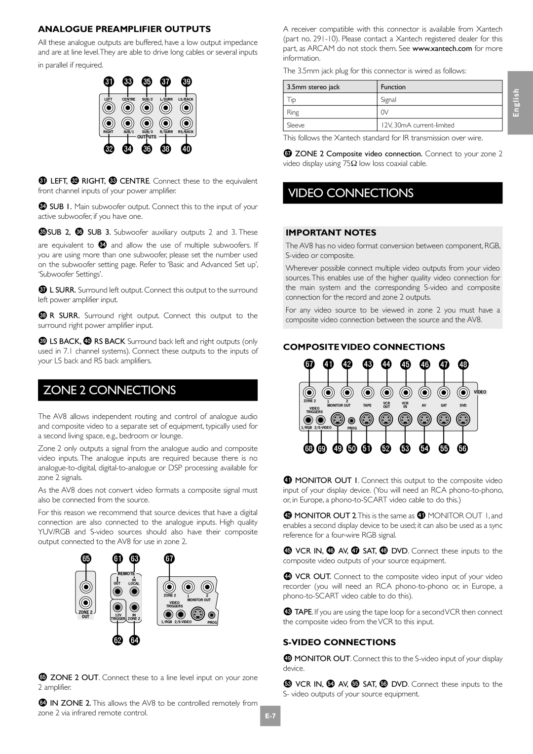
Audio Connections
Analogue Audio Inputs
Analogue Record Outputs Digital Audio Inputs
Video Connections
Zone 2 Connections
High Quality Component Video Connections
RGB 4-wire connection
Control Connections
Trigger Outputs
Plugging
Connecting to a Power Supply
Wrong PLUG?
Mains Lead
Configuring the AV8
General Settings
Basic Setup
Speaker Sizes
Distance measurements for 5.1 Speaker delay settings
Speaker Delay Settings
Level Settings
Subwoofer Settings
Boundary Gain Compensation
THX Settings
Saving Settings and Exit Setup
Save Setup
ADV 1 Speaker EQ
Advanced Setup
ADV 2 Video Settings
ADV 3 Digital Settings
Enabled sources are listed on the ‘Access’ line of the OSD
ADV 4 Zone 2 Settings
ADV 5 Input Trims
Saving Settings and Exiting Setup
THX. Selects between the available THX modes
Front panel controls
Remote control
Operating your AV8
Using the Controls
EFFECTS/FX
Volume Control
Headphones
Stereo Direct
Using the Main Menu Screen
Pro Logic II Music Mode
Control VIA Zone 2 Menu
Using Zone
Different volume level from the main zone zone
CR80 remote control
Introduction
Surround modes
TWO-CHANNEL Source Modes
Multichannel Source Modes
Multichannel Sources
THX Modes
THX Standards
DSP Effects Modes
About THX Cinema Processing
THX Technology
Troubleshooting
No zone 2 audio when playing DTS film
Source switching changes randomly or freezes on one source
Unable to alter settings in Setup Menus
Feedback when making digital recording
Unable to adjust balance control
Unable to adjust bass and treble controls
Balance is not available in THX mode
Continual Improvement Policy
Technical specifications
Radio Interference
Processing Component Specifications
Locking the Setup Menu
Additional technical information
Scart RGB cable with audio back to processor
Scart Connections
Scart S-video cable with audio back to processor
Table of Remote Codes
IR Remote Codes
Example for programming Display = RC-5 code
Query Commands
Setting Values
Command Processing
Cinema, 6 = Neo6 Music
Command Parameters Description Response
Query Volume
Mode, *Effect Mode, *THX Mode
Main Menu Commands
General Operation Commands
Basic Speakers
Setup Commands Basic
Basic Delay
Basic General
Basic THX
Basic Sub
Setup Commands Advanced
Navigation
Engineering Settings
Menu Access
Multi-button Presses
AV8 Programmer
Utility Software
Claims Under Guarantee
Guarantee
Worldwide Guarantee
Warranty Covers
Français
Normes DE Sécurité
Consignes de sécurité
Respect DES Consignes DE Sécurité
Sécurité
Bienvenue au Préamplificateur-processeur AV8
Table DES Matières
Utilisation DE CE Manuel
Remarques Concernant LES Raccordements
Mise EN Place DE L’APPAREIL
Vidéo
Câbles
Installation DES Enceintes
Raccordements Audio
Remarques Importantes
Raccordements Zone
Raccordementsvidéo
Sorties Préamplificateur Analogiques
Raccordements Vidéo Haute Qualité Composantes
Raccordements DE Commande
Sorties Trigger Commutateur
Raccordements S-VIDÉO
Branchement
Raccordement Secteur
LA Fiche Secteur EST-ELLE LA Bonne ?
Cordon Secteur
Réglage de l’AV8
Remarque sur la taille des enceintes
General Settings Réglages Divers
Réglages DE Base
Speaker Sizes Taille DES Enceintes
Level Settings Réglages DES Niveaux
Speaker Delay Settings Réglages DES Retards Enceintes
THX Settings Réglages THX
Subwoofer Settings Réglages DES Caissons DE Grave
ADV 1 Speaker EQ. Réglages DE Tonalité
ADV 2 Video Settings Réglages Vidéo
Réglages Avancés
Mémoriser ET Quitter LES Réglages
ADV 4 Zone 2 Settings Réglages Zone
ADV 3 Digital Settings Réglages Numériques
ADV 5 Input Trims Réglages Fins DES Entrées
Commandes sur la face avant
Avant d’utiliser la télécommande
Télécommande
TRM réglage des enceintes
Utilisation de l’AV8
Commandes
Écoute AU Casque
Réglage DU Volume
Utilisation DES Magnétoscopes
Stéréo Direct
Main Menu Screen 1 Menu Principal
Utilisation DE LA Télécommande
Utilisation DES Commandes SUR LA Face Avant
Menus Principaux
II Music des sources à deux canaux
Main Menu Screen 2 Menu Principal
Main Menu Screen 3 Menu Principal
Utilisation DE LA Zone
Zone 2 Main Menu Menu Principal Zone
Modes Pour Sources Numériques
Mémoire Mode
Modes surround
Modes Source À Deux Canaux
Modes Source Multicanal
Sources Multicanal
Modes THX
Normes THX
Modes Effets DSP
Traitement Cinéma THX
Technologie THX
Dépannage
Seule une connexion vidéo composantes relie l’AV8 à l’écran
Il y a du ronflement sur une entrée analogique
La réception radio ou télévision est perturbée
La Zone 2 modifie les entrées source de la Zone principale
Il est impossible de modifier la balance
Ce réglage n’est pas disponible en mode THX
Le format de l’image vidéo est anormal dans la Zone
Il est impossible de modifier les réglages de tonalité
Politique D’AMÉLIORATION Continue
Spécifications techniques
Programmation VIA L’ENTRÉE RS232
Informations techniques complémentaires
Interférence Radio
Spécifications DES Circuits Processeurs
Câble Scart RVB avec retour audio vers le processeur
Connexions Scart
Câble Scart S-Vidéo avec retour audio vers le processeur
Table DES Codes Télécommande
Codes Télécommande IR
Exemple de programmation Display = Code RC-5
Réglage DES Valeurs
Commandes D’INTERROGATION
Traitement DES Commandes
Interface Sérielle DE Programmation DE L’AV8
Interroger mode
Commande Paramètres Description Réponse
Interroger mode effet EFFy, où y varie de 0 à
Interroger mode THX THXy, où y varie de 0 à
Commandes Menu Principal
Commandes DE Fonctionnenment Général
Commandes de base Retards
Réglages Commandes DE Base
Commandes de base générales
Commandes de base Enceintes
Commandes de base THX
Commandes de base Caisson de grave
Réglages Commandes Avancées
Commandes avancées Navigation
Commandes avancées Réglages techniques
Commandes avancées Touches multiples
Commandes avancées Accès aux menus
Programmateur AV8
Outil Logiciel
Enregistrement SUR Internet
Garantie
Deutsch
Wichtige Sicherheitsanweisungen
Sicherheitsrichtlinien
Einhaltung VON Sicherheitsbestimmungen
Sicherheit
Willkommen
Inhalt
Hinweise ZUM Handbuch
Serielle Steuer Digitale
Aufstellen des Geräts
Aufstellen DES Geräts
Hinweis ZU DEN Anschlüssen
Aufstellen DER Lautsprecher
Kabel
Audioanschlüsse
Analoge Vorverstärkerausgänge
Anschlüsse FÜR Zone
Videoanschlüsse
Videoanschlüsse
Wichtige Hinweise
COMPOSITE-VIDEOANSCHLÜSSE
Die Trigger-Ausgänge verschiedene Funktionen
Steueranschlüsse
TRIGGER-AUSGÄNGE
Ctrl oder „SCART im Menü
Modus „Screen Ctrl
Falscher NETZSTECKER?
Netzkabel
Hinweise zum SCART-Modus
Konfigurieren des AV8
Hinweis zum Lautsprecherformat
General Settings Allgemeine Einstellungen
Basic Grundeinstellungen
Speaker Sizes Lautsprecherformat
Speaker Config Custom
Subwoofer Settings SUBWOOFER- Einstellungen
Level Settings Pegeleinstellungen
Boundary Gain Compensation Grenzverstärkungsausgleich
Save Setup Setup speichern
Beenden ohne Speichern
ADV 3 Digital Settings Digitale Einstellungen
ADV 2 Video Settings Videoeinstellungen
ADV 1 Speaker EQ. LAUTSPRECHER- Equalizer
ADV 5 Input Trims EINGANGS-TRIMMS
ADV 4 Zone 2 Settings Einstellungen FÜR Zone
Speichern DER Einstellungen UND Beenden DES SETUP-MENÜS
Hauptregler. Der Hauptregler hat zwei Funktionen
Die Bedienelemente an der Gerätevorderseite
Sie in der Dokumentation zur CR80
Die Fernbedienung
DIE Bedienelemente
Betrieb des AV8
Lautstärkeregelung
Videorekorder
Kopfhörer
Hauptmenü Seite
DAS Hauptmenü
Über DIE Fernbedienung
Mute Über DIE Gerätevorderseite
Hinweis Im THX-Modus können Sie die Balance nicht ändern
Pro Logic II Music Mode Pro Logic II-Musikmodus
Compression Komprimierung Hier können Sie unter zwei Komp
Steuerung Über DAS Zone 2 Main Menu Zone 2-HAUPTMENÜ
Zone
Zone 1 Status Zustand von Zone 1 Hier wird der Zustand von
Einführung
Surround-Modi
Zweikanalmodi
Wiedergabe VON 5.1-QUELLEN AUF Lautsprechersystemen
Mehrkanalquellen
Mehrkanalmodi
THX-MODI
THX-NORMEN
DSP-EFFEKTMODI
Verarbeitung MIT THX Cinema
THX-VERFAHREN
Fehlerbehebung
Component-Videoverbindung nur mit dem AV8
Brummen an einem analogen Eingang
Der Radio- bzw. Fernsehempfang ist gestört
Zone 2 ändert die Eingänge in der Hauptzone
Regeln der Balance nicht möglich
Kein Ton in Zone 2 bei der Wiedergabe eines DTS-Films
Ungewöhnliches Seitenverhältnis des Bilds in Zone
Tiefen und Höhen können nicht geregelt werden
Laufende Verbesserungen
Technische Daten
Programmieren Über DEN RS232-EINGANG
Weitere technische Informationen
Störungen Funkinterferenzen
Technische Daten DER Verarbeitungskomponenten
Scart-RGB-Kabel mit Audio zurück zum Prozessor
SCART-ANSCHLÜSSE
Scart-S-Videokabel mit Audio zurück zum Prozessor
Codes DER Fernbedienung
Codes FÜR DIE IR-FERNBEDIENUNG
Programmierungsbeispiel Anzeige = RC-5 Code
Wobei lf der ASCII-Zeilenumbruch ist
Einstellen VON Werten
Abfragebefehle
Befehlsverarbeitung
Abfragen
Befehl Parameters Beschreibung Ausgabe
Ein/Aus abfragen ZPWRx, wobei z die angegebene Zone ist
ZMUTx, wobei z die angegebene Zone ist
Befehle DES Hauptmenüs
Allgemeine Betriebsbefehle
HQ-Video Zwischen 0 und 1 liegen kann = RGB, 1 = Component
Befehle DES SETUP-MENÜS Basic
Basic Level Settings Grundeinstellungen Pegeleinstellungen
Basic Speaker Sizes Grundeinstellungen Lautsprecherformat
Basic THX Settings Grundeinstellungen THX Settings
Save Settings Einstellungen Speichern
Befehle DES SETUP-MENÜS Advanced
Adv 5 Input Trims Erweitertes Einrichten Eingangs-Trimms
Pfeiltasten
Engineering Settings Technikeinstellungen
Drücken mehrerer Tasten
Menüzugriff
Dienstprogramm
DIE Garantie Umfasst Folgendes
PROBLEME?
ONLINE-REGISTRIERUNG
Weltweite Garantie
Nederlands
Veiligheidsvoorschriften
Veiligheidsrichtlijnen
Veiligheidsnaleving
Veiligheid
Welkom bij de AV8 Voorversterker Processor
Inhoudsopgave
Deze Handleiding Gebruiken
Sturings
Installatie
DE Eenheid Plaatsen
Notas Betreffende DE Aansluitingen
Kabels
Luidsprekerinstallatie
AUDIO-AANSLUITINGEN
Belangrijke NOTA’S
Zone 2 Aansluitingen
Video Aansluiting
Analoge Voorversterkeruitgangen
Kan geen component en RGB bronnen mengen
Controle Aansluitingen
Video Aansluitingen
Hoge Kwaliteit Component Video Aansluitingen
Sturingsuitgangen
Nota’s betreffende de Scart mode
Schermcontrole mode
Nota’s betreffende de schermcontrole mode
Aansluiten
Aansluiting OP HET Lichtnet
Verkeerde Stekker ?
Netsnoer
Afstelmenu
Uw AV8 configureren
Toegang TOT HET Afstelmenu
Instellingsvergrendeling
Luidspreker Eigenschappen Speaker Sizes
Algemene Instellingen General Settings
Basisinstelling
Navigatie VIA HET Frontpaneel
Niet in het vorig ‘Speaker Sizes’ menu geselecteerd werd
Luisterstand
Subwoofer Instellingen Subwoofer Settings
Niveau Instellingen Level Settings
DE Instellingen Opslaan EN DE SET-UP Verlaten
THX Instellingen THX Settings
ADV 3 Digitale Instellingen Digital Settings
ADV 2 Video Instellingen Video Settings
Geavanceerde Instelling
ADV 5 Ingangsinstellingen Inputtrims
ADV 4 Zone 2 Instellingen Zone 2 Settings
DE Instellingen Opslaan EN DE SET-UP Verlaten
Controleknop. Deze controleknop verzekert twee functies
Knoppen aan de voorkant
Samen met de6EFFECT toets en de5MODE toetsen gebruikt wordt
Voor verdere informatie betreffende het gebruik van de
Afstandsbediening
Wordt
Gebruikvan DE Regelingen
Uw AV8 bedienen
Koptelefoons
Volumeregeling
VCR-WERKING
Stereo Rechtstreeks
Hoofdmenu Scherm
Gebruikvan HET Hoofdmenu Scherm
Gebruik VAN DE Afstandsbediening
Gebruik VAN HET Frontpaneel
Nota In direct mode is geen digitale uitgang beschikbaar
Video Input Duidt de huidige Geselecteerde video
Gebruikvan Zone
Controle VIA DE Zone 2 Menu
Ingesteld worden
Modes Voor Digitale Bronnen
Mode Geheugen
Inleiding
Tweekanaalsbronnen Modes
Meerdere Kanalenbronnen Modes
Meerdere Kanalen Bronnen
DSP Effect Modes
THX Muziek mode
THX Surround EX en Surround ES
THX Technologie
THX Cinema Processing Informatie
THX Normen
Problemen oplossen
Kan een bepaalde ingang in zone 2 niet selecteren
Brom op een analoge ingang
Er ontstaan radio en televisie interferenties
Zone 2 verandert de broningangen in de hoofdzone
De balans kan niet ingesteld worden
De balansregeling is in THX mode niet beschikbaar
Geen zone 2 audio bij de weergave van een DTS film
Rare aspectverhouding van de video in zone
Digitale ingangen
Technische specificaties
Beleid Voor Voortdurende Verbetering
Video-ingangen en -uitgangen
Processingcomponenten Specificaties
Bijkomende technische informatie
Radiostoring
HET SET-UP Menu Vergrendelen
Scart RGB kabel met audio retour naar de processor
Scart Aansluitingen
Scart S-Video kabel met audio retour naar de processor
Afstandsbediening Codes Tabel
IR Afstandsbedieningcodes
Programmatievoorbeeld Display = RC-5 code
Instelwaarden
VRAAGCOMMANDO’S Query
Commandobehandeling
AV8 Seriele Programmatie Interface
OPVRAAGCOMMANDO’S Query
Hoofdmenu COMMANDO’S
COMMANDO’S Algemene Werking
Basis niveaus
SET-UP COMMANDO’S Basis
Basis luidsprekers
Basis vertraging
Basis THX
Basis Sub
SET-UP COMMANDO’S Geavanceerd
Navigatie
Engineering instellingen
Meerdere toetsen drukacties
Menutoegang
AV8 Programmeerder
Upgrade Software
Claims Onder Garantie
ONLINE-REGISTRATIE
Universele Garantie
DE Garantie Dekt
Page
Page
Pembroke AVENUE, WATERBEACH, Cambridge CB5 9QR, England