Task 7B: Install a Terminal via Modems
This task describes how to connect a terminal via a modem to Admin/Port B of the MFB. (This task can also be used for remote connection to the TN2170
To make sure the modems that you are installing are on the list of supported peripherals, see Appendix B, ‘‘Supported Terminals and Modems/Option Settings.’’
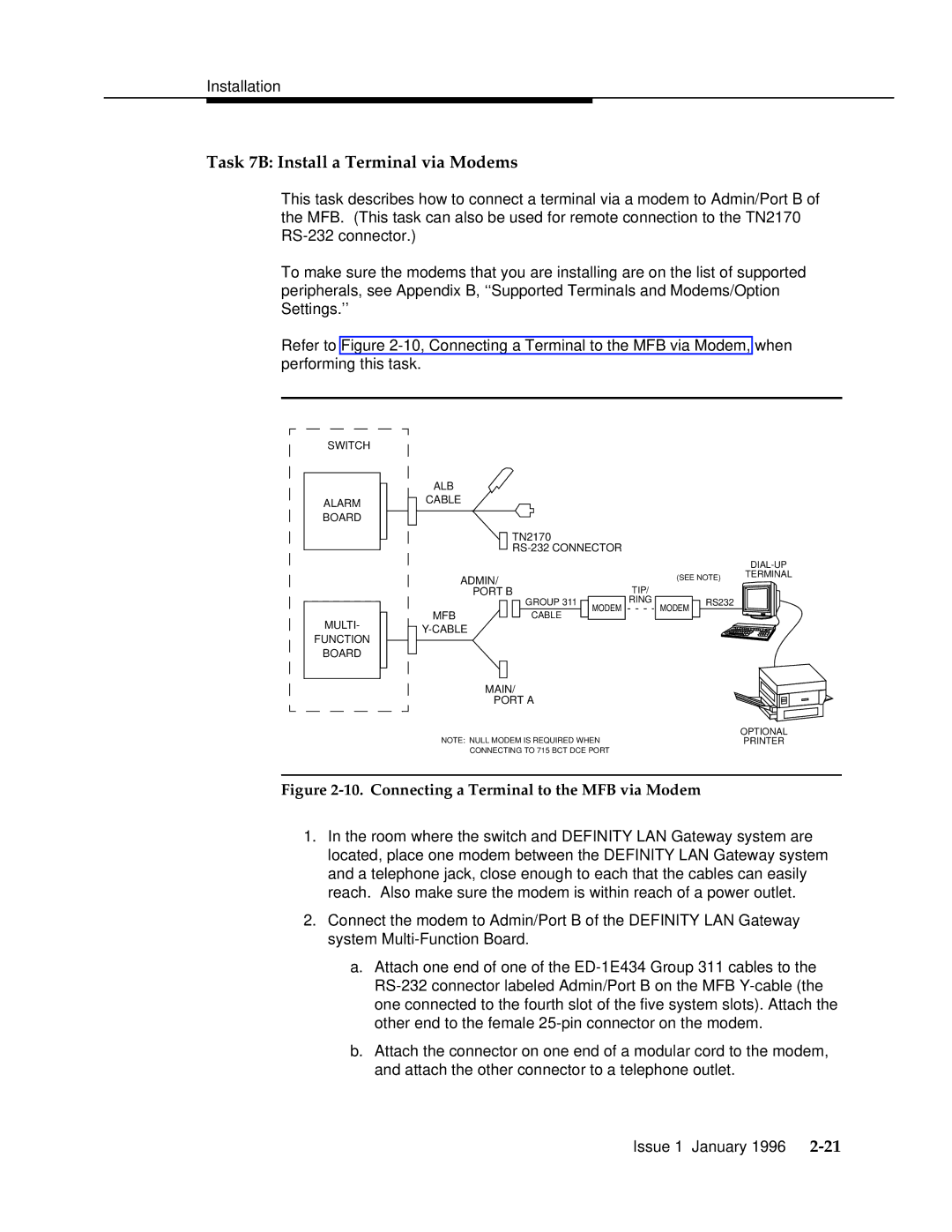
Refer to Figure
SWITCH
ALARM BOARD
ALB
CABLE
TN2170
ADMIN/ | TIP/ |
PORT B |
| |
(SEE NOTE) | TERMINAL |
|
MULTI-
FUNCTION
BOARD
|
|
|
| GROUP 311 |
| MODEM | RING |
MFB |
|
|
| CABLE |
|
|
|
|
|
|
|
|
| ||
|
|
|
| ||||
MODEM
RS232
MAIN/
PORT A
| OPTIONAL |
NOTE: NULL MODEM IS REQUIRED WHEN | PRINTER |
CONNECTING TO 715 BCT DCE PORT |
|
Figure 2-10. Connecting a Terminal to the MFB via Modem
1.In the room where the switch and DEFINITY LAN Gateway system are located, place one modem between the DEFINITY LAN Gateway system and a telephone jack, close enough to each that the cables can easily reach. Also make sure the modem is within reach of a power outlet.
2.Connect the modem to Admin/Port B of the DEFINITY LAN Gateway system
a.Attach one end of one of the
b.Attach the connector on one end of a modular cord to the modem, and attach the other connector to a telephone outlet.
Issue 1 January 1996