Task 1: Verify the Selected Site
![]()
![]() NOTE:
NOTE:
Defining the system requirements and ensuring that the site meets these requirements are the responsibility of the Project Manager and the customer and must be completed before you install the DEFINITY LAN Gateway system. However, the guidelines are listed here so that you are aware of these requirements.
Verify that the site selected for the DEFINITY switch and the DEFINITY LAN Gateway system provides the following:
A DEFINITY Generic 3V4 switch, or DEFINITY Generic 3V4 software that incorporates a field maintenance upgrade for G3V2/V3.
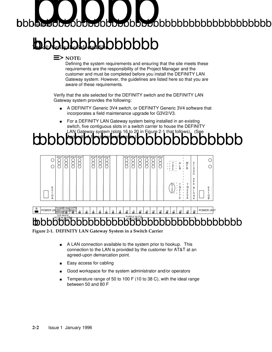
For a DEFINITY LAN Gateway system being installed in an existing switch, five contiguous slots in a switch carrier to house the DEFINITY LAN Gateway system (slots 16 to 20 in Figure
.
6 ..
3 .
1 . D .. A .
AT&T
.
.
.
.
.
.
.
.
AT&T AT&T AT&T
. | . | . |
. | . | . |
. | . | . |
. | . | . |
. | . | . |
. | . | . |
. | . | . |
. | . | . |
AT&T AT&T AT&T
. | . | . |
. | . | . |
. | . | . |
. | . | . |
. | . | . |
. | . | . |
. | . | . |
. | . | . |
AT&T AT&T AT&T AT&T AT&T AT&T
. | . | . | . | . | . |
. | . | . | . | . | . |
. | . | . | . | . | . |
. | . | . | . | . | . |
. | . | . | . | . | . |
. | . | . | . | . | . |
. | . | . | . | . | . |
. | . | . | . | . | . |
T | A | M |
A | L | F |
P | B | B |
E | ||
| T | T |
D | ||
I | N | N |
S | 2 | 2 |
K | 1 | 2 |
| ||
| 7 | 0 |
| 0 | 8 |
Z 1 0 0 C
A P P.
B L A N K
.
6 ..
3 .
1 . D .. B .
B
POWER UNIT
POWER | TONE- | EXPN | ||||
UNIT | CLOCK | INTFC | ||||
SERVICE | 1 |
| 2 |
| ||
|
|
|
|
|
| |
3
4
5 6 7
8
9
10 | 11 |
| 12 | 13 | 14 | 15 | |||||||||
|
|
|
|
|
|
|
|
|
|
|
|
|
|
|
|
16
17 18
19
20
POWER UNIT
TOP WHITE
BOTTOM PURPLE
TWO SLOTS
PURPLE SLOTS (PORT SLOTS)
Figure 2-1. DEFINITY LAN Gateway System in a Switch Carrier
A LAN connection available to the system prior to hookup. This connection to the LAN is provided by the customer for AT&T at an
Easy access for cabling
Good workspace for the system administrator and/or operators
Temperature range of 50 to 100 F (10 to 38 C), with the ideal range between 50 and 80 F