Maintenance
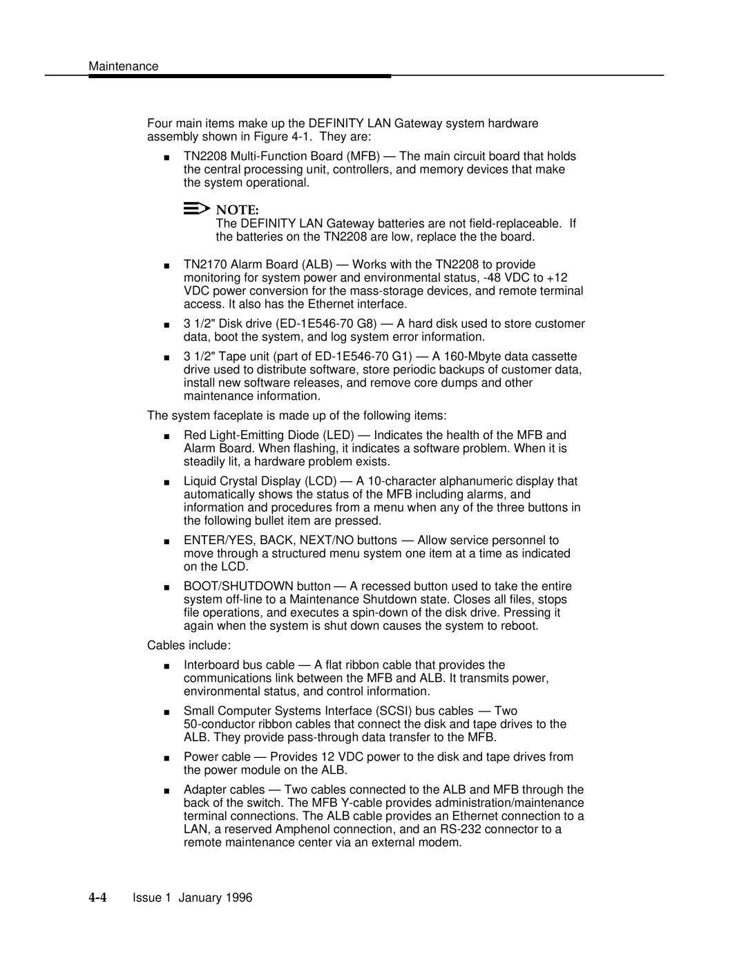
Four main items make up the DEFINITY LAN Gateway system hardware assembly shown in Figure 4-1.They are:
TN2208 Multi-Function Board (MFB) — The main circuit board that holds the central processing unit, controllers, and memory devices that make the system operational.

 NOTE:
NOTE:
The DEFINITY LAN Gateway batteries are not field-replaceable. If the batteries on the TN2208 are low, replace the the board.
TN2170 Alarm Board (ALB) — Works with the TN2208 to provide monitoring for system power and environmental status, -48 VDC to +12 VDC power conversion for the mass-storage devices, and remote terminal access. It also has the Ethernet interface.
3 1/2" Disk drive (ED-1E546-70 G8) — A hard disk used to store customer data, boot the system, and log system error information.
3 1/2" Tape unit (part of ED-1E546-70 G1) — A 160-Mbyte data cassette drive used to distribute software, store periodic backups of customer data, install new software releases, and remove core dumps and other maintenance information.
The system faceplate is made up of the following items:
Red Light-Emitting Diode (LED) — Indicates the health of the MFB and Alarm Board. When flashing, it indicates a software problem. When it is steadily lit, a hardware problem exists.
Liquid Crystal Display (LCD) — A 10-character alphanumeric display that automatically shows the status of the MFB including alarms, and information and procedures from a menu when any of the three buttons in the following bullet item are pressed.
ENTER/YES, BACK, NEXT/NO buttons — Allow service personnel to move through a structured menu system one item at a time as indicated on the LCD.
BOOT/SHUTDOWN button — A recessed button used to take the entire system off-line to a Maintenance Shutdown state. Closes all files, stops file operations, and executes a spin-down of the disk drive. Pressing it again when the system is shut down causes the system to reboot.
Cables include:
Interboard bus cable — A flat ribbon cable that provides the communications link between the MFB and ALB. It transmits power, environmental status, and control information.
Small Computer Systems Interface (SCSI) bus cables — Two
50-conductor ribbon cables that connect the disk and tape drives to the ALB. They provide pass-through data transfer to the MFB.
Power cable — Provides 12 VDC power to the disk and tape drives from the power module on the ALB.
Adapter cables — Two cables connected to the ALB and MFB through the back of the switch. The MFB Y-cable provides administration/maintenance terminal connections. The ALB cable provides an Ethernet connection to a LAN, a reserved Amphenol connection, and an RS-232 connector to a remote maintenance center via an external modem.