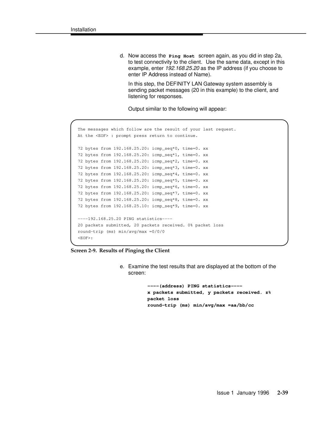
d.Now access the Ping Host screen again, as you did in step 2a, to test connectivity to the client. Use the same data, except in this example, enter 192.168.25.20 as the IP address (if you choose to enter IP Address instead of Name).
In this step, the DEFINITY LAN Gateway system assembly is sending packet messages (20 in this example) to the client, and listening for responses.
Output similar to the following will appear:
The messages which follow are the result of your last request.
At the <EOF> : prompt press return to continue.
72 bytes from 192.168.25.20: icmp_seq*0, time=0. xx
72 bytes from 192.168.25.20: icmp_seq*1, time=0. xx
72 bytes from 192.168.25.20: icmp_seq*2, time=0. xx
72 bytes from 192.168.25.20: icmp_seq*3, time=0. xx
72 bytes from 192.168.25.20: icmp_seq*4, time=0. xx
72 bytes from 192.168.25.20: icmp_seq*5, time=0. xx
72 bytes from 192.168.25.20: icmp_seq*6, time=0. xx
72 bytes from 192.168.25.20: icmp_seq*7, time=0. xx
72 bytes from 192.168.25.20: icmp_seq*8, time=0. xx
72 bytes from 192.168.25.10: icmp_seq*9, time=0. xx
20 packets submitted, 20 packets received. 0% packet loss
<EOF>:
Screen 2-9. Results of Pinging the Client
e.Examine the test results that are displayed at the bottom of the screen:
x packets submitted, y packets received. z%
packet loss
Issue 1 January 1996
