SWITCH
ALARM
BOARD
MULTI-
FUNCTION
ALB
CABLE
ADMIN/
PORT B
MFB
GROUP 311
CABLE
7400A
(SEE
NETWORK 7400B CONNECTIONS
BOARD
POWER
SUPPLY
MAIN/
PORT A
POWER SUPPLY
NOTE: NULL MODEM IS REQUIRED WHEN
CONNECTING TO 715 BCT DCE PORT
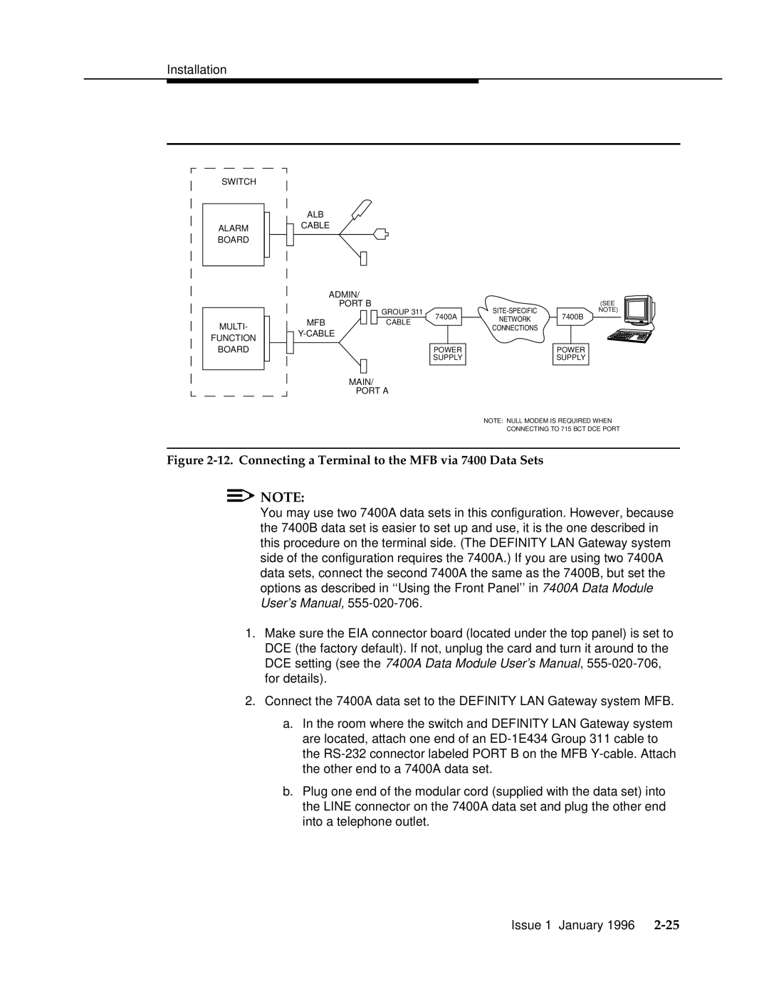
Figure 2-12. Connecting a Terminal to the MFB via 7400 Data Sets
![]()
![]() NOTE:
NOTE:
You may use two 7400A data sets in this configuration. However, because the 7400B data set is easier to set up and use, it is the one described in this procedure on the terminal side. (The DEFINITY LAN Gateway system side of the configuration requires the 7400A.) If you are using two 7400A data sets, connect the second 7400A the same as the 7400B, but set the options as described in ‘‘Using the Front Panel’’ in 7400A Data Module User’s Manual,
1.Make sure the EIA connector board (located under the top panel) is set to DCE (the factory default). If not, unplug the card and turn it around to the DCE setting (see the 7400A Data Module User’s Manual,
2.Connect the 7400A data set to the DEFINITY LAN Gateway system MFB.
a.In the room where the switch and DEFINITY LAN Gateway system are located, attach one end of an
b.Plug one end of the modular cord (supplied with the data set) into the LINE connector on the 7400A data set and plug the other end into a telephone outlet.
Issue 1 January 1996