Chapter 5 Maintaining the Router
Removing and Replacing AC and DC Power Subsystem Components
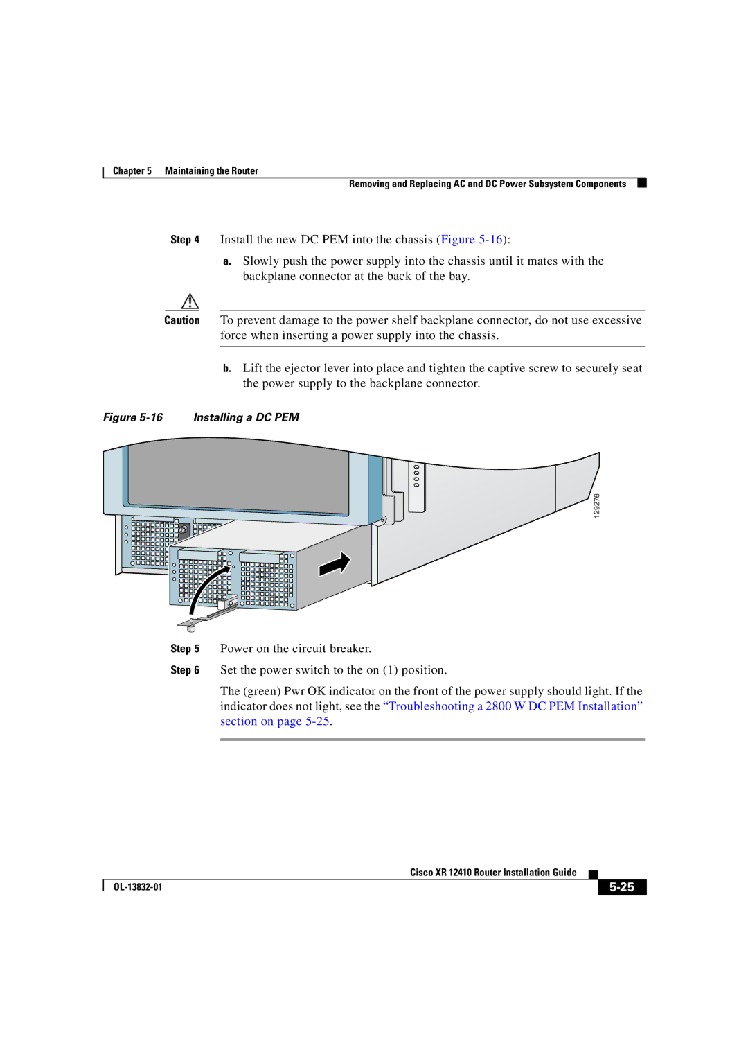
Step 4 Install the new DC PEM into the chassis (Figure
a.Slowly push the power supply into the chassis until it mates with the backplane connector at the back of the bay.
Caution To prevent damage to the power shelf backplane connector, do not use excessive force when inserting a power supply into the chassis.
b.Lift the ejector lever into place and tighten the captive screw to securely seat the power supply to the backplane connector.
Figure 5-16 Installing a DC PEM
129276
Step 5 Power on the circuit breaker.
Step 6 Set the power switch to the on (1) position.
The (green) Pwr OK indicator on the front of the power supply should light. If the indicator does not light, see the “Troubleshooting a 2800 W DC PEM Installation” section on page
|
| Cisco XR 12410 Router Installation Guide |
|
|
|
|
| ||
|
|
|
| |
|
|
|