Chapter 2 Preparing for Installation
Site Requirement Guidelines
Air Flow Guidelines
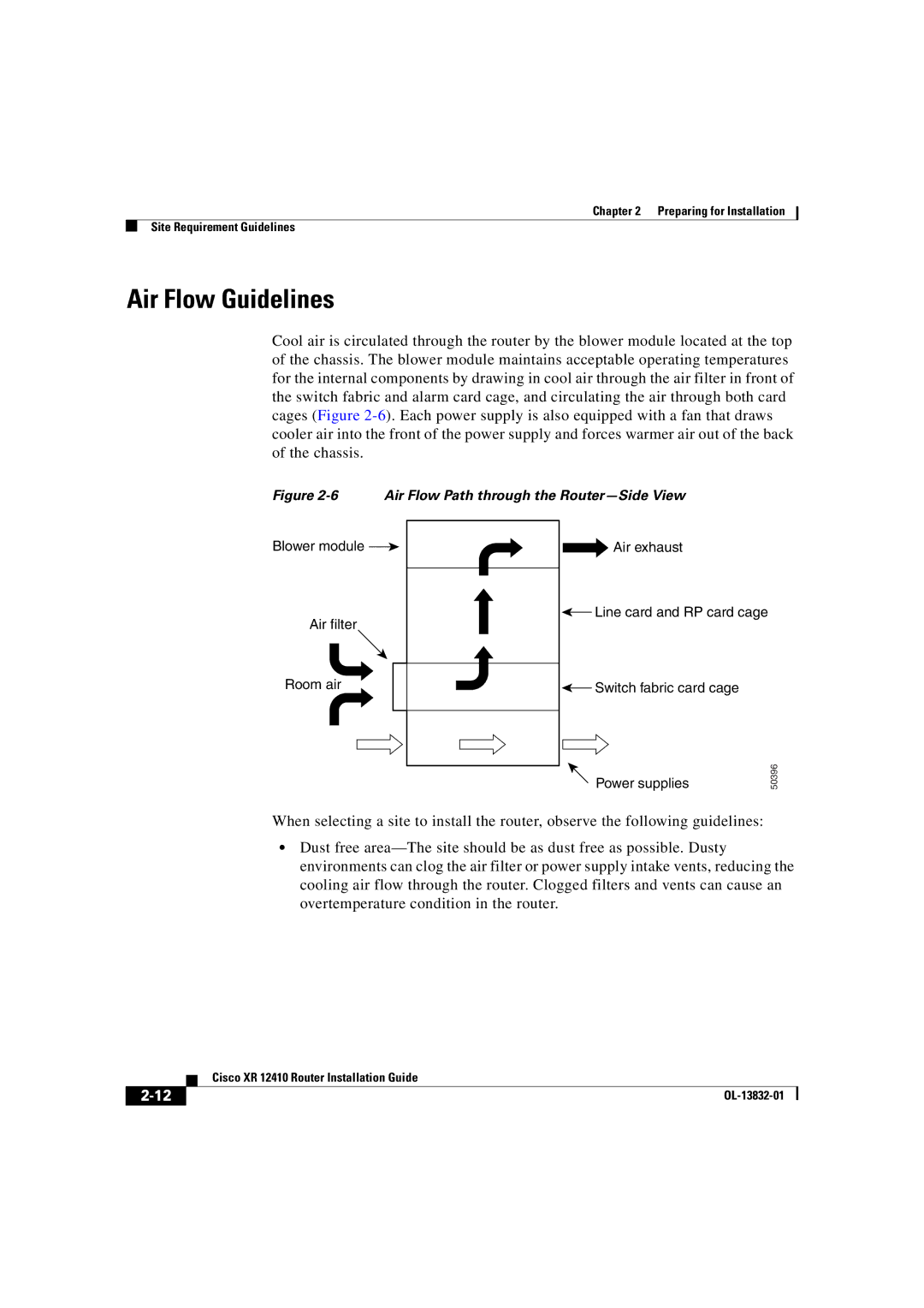
Cool air is circulated through the router by the blower module located at the top of the chassis. The blower module maintains acceptable operating temperatures for the internal components by drawing in cool air through the air filter in front of the switch fabric and alarm card cage, and circulating the air through both card cages (Figure
Figure 2-6 Air Flow Path through the Router—Side View
Blower module ![]()
Air filter
Room air
Air exhaust
![]() Line card and RP card cage
Line card and RP card cage
![]() Switch fabric card cage
Switch fabric card cage
Power supplies
50396
When selecting a site to install the router, observe the following guidelines:
•Dust free
| Cisco XR 12410 Router Installation Guide |
|
