Chapter 2 Preparing for Installation
Alarm Display Connection Guidelines
Table
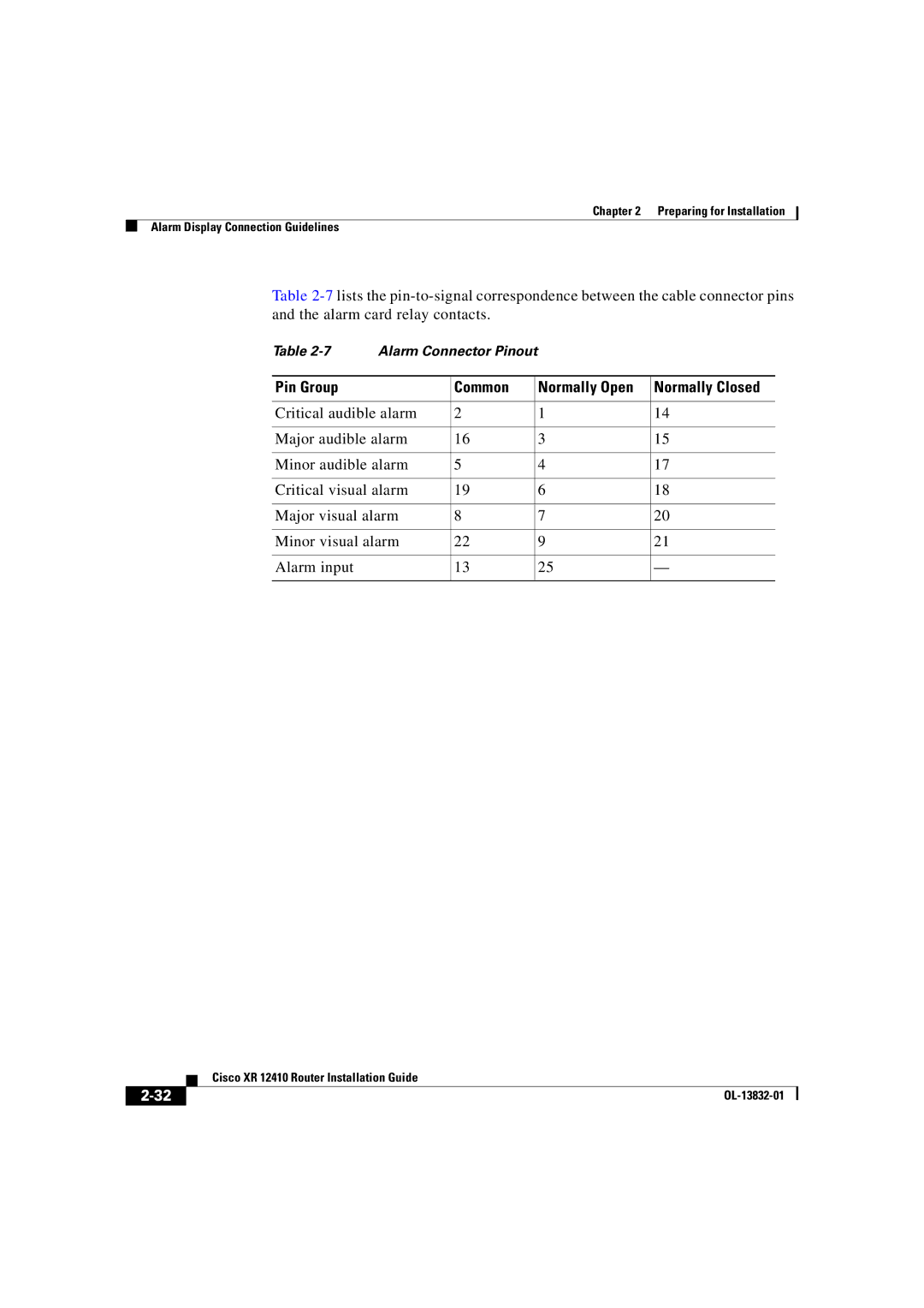
Table | Alarm Connector Pinout |
|
| ||
|
|
|
|
|
|
Pin Group |
| Common |
| Normally Open | Normally Closed |
|
|
|
|
| |
Critical audible alarm | 2 |
| 1 | 14 | |
|
|
|
|
| |
Major audible alarm | 16 |
| 3 | 15 | |
|
|
|
|
| |
Minor audible alarm | 5 |
| 4 | 17 | |
|
|
|
|
| |
Critical visual alarm | 19 |
| 6 | 18 | |
|
|
|
|
| |
Major visual alarm | 8 |
| 7 | 20 | |
|
|
|
|
| |
Minor visual alarm | 22 |
| 9 | 21 | |
|
|
|
|
|
|
Alarm input |
| 13 |
| 25 | — |
|
|
|
|
|
|
| Cisco XR 12410 Router Installation Guide |
|
