Chapter 1 Cisco XR 12410 Router Overview
Physical and Functional Description of Router
Each AC PEM converts 200 to 240 VAC into
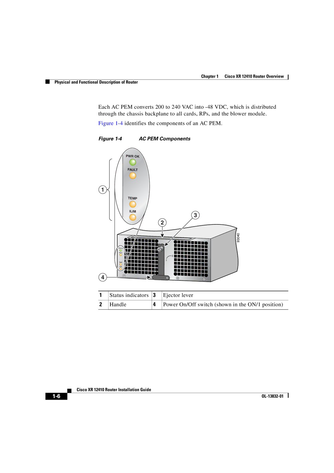
Figure 1-4 identifies the components of an AC PEM.
Figure 1-4 AC PEM Components
PWR OK
FAULT
1
| TEMP |
|
|
| ILIM |
| 3 |
|
|
| |
|
|
| 2 |
|
|
| 93040 |
| PWR OK |
|
|
| FAULT |
|
|
|
|
| 0 |
| TEMP |
|
|
| ILIM |
|
|
4 |
|
|
|
1 | Status indicators | 3 | Ejector lever |
2 | Handle | 4 | Power On/Off switch (shown in the ON/1 position) |
| Cisco XR 12410 Router Installation Guide |