Chapter 2 Preparing for Installation
Alarm Display Connection Guidelines
Alarm Display Connection Guidelines
The router alarm system consists of the following cards:
•Two alarm cards—Installed in the switch fabric and alarm card cage. They do not have any indicators, connectors, or switches.
•One alarm display card—Mounted on the front of the router chassis, just above the horizontal cable management tray.
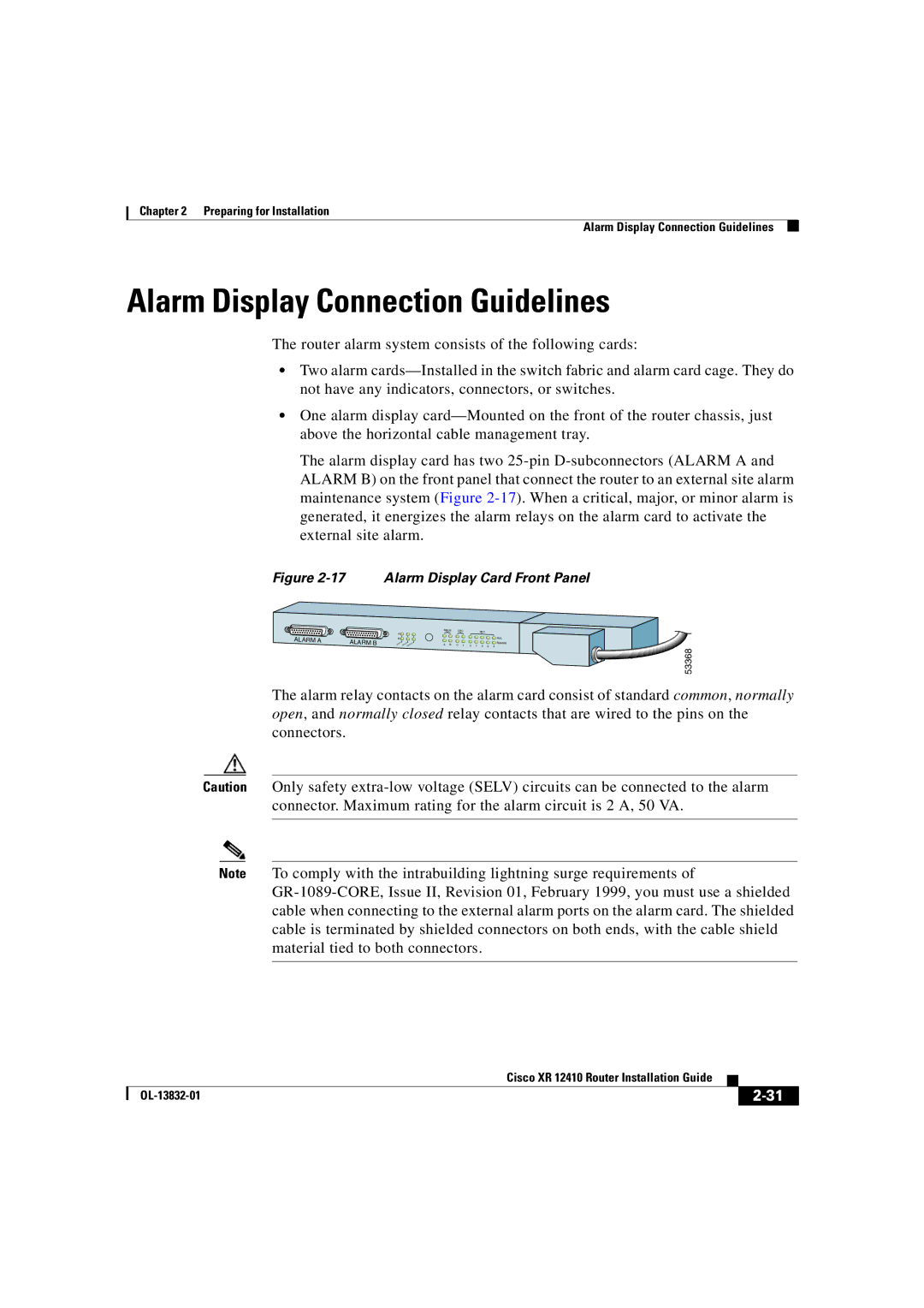
The alarm display card has two 25-pin D-subconnectors (ALARM A and ALARM B) on the front panel that connect the router to an external site alarm maintenance system (Figure 2-17). When a critical, major, or minor alarm is generated, it energizes the alarm relays on the alarm card to activate the external site alarm.
Figure 2-17 Alarm Display Card Front Panel
MBUS | CSC | | | SFC | | |
A | | | | | | | | |
B | | | | | | | | FAIL |
A | B | 0 | 1 | 0 | 1 | | | ENABLE |
2 | 3 | 4 |
53368
The alarm relay contacts on the alarm card consist of standard common, normally open, and normally closed relay contacts that are wired to the pins on the connectors.
Caution Only safety extra-low voltage (SELV) circuits can be connected to the alarm connector. Maximum rating for the alarm circuit is 2 A, 50 VA.
Note To comply with the intrabuilding lightning surge requirements of GR-1089-CORE, Issue II, Revision 01, February 1999, you must use a shielded cable when connecting to the external alarm ports on the alarm card. The shielded cable is terminated by shielded connectors on both ends, with the cable shield material tied to both connectors.
| | Cisco XR 12410 Router Installation Guide | | |
| | |
| OL-13832-01 | | | 2-31 |
| | |