Chapter 3 Installing the Cisco XR 12410 Router
Removing Cards from the Chassis
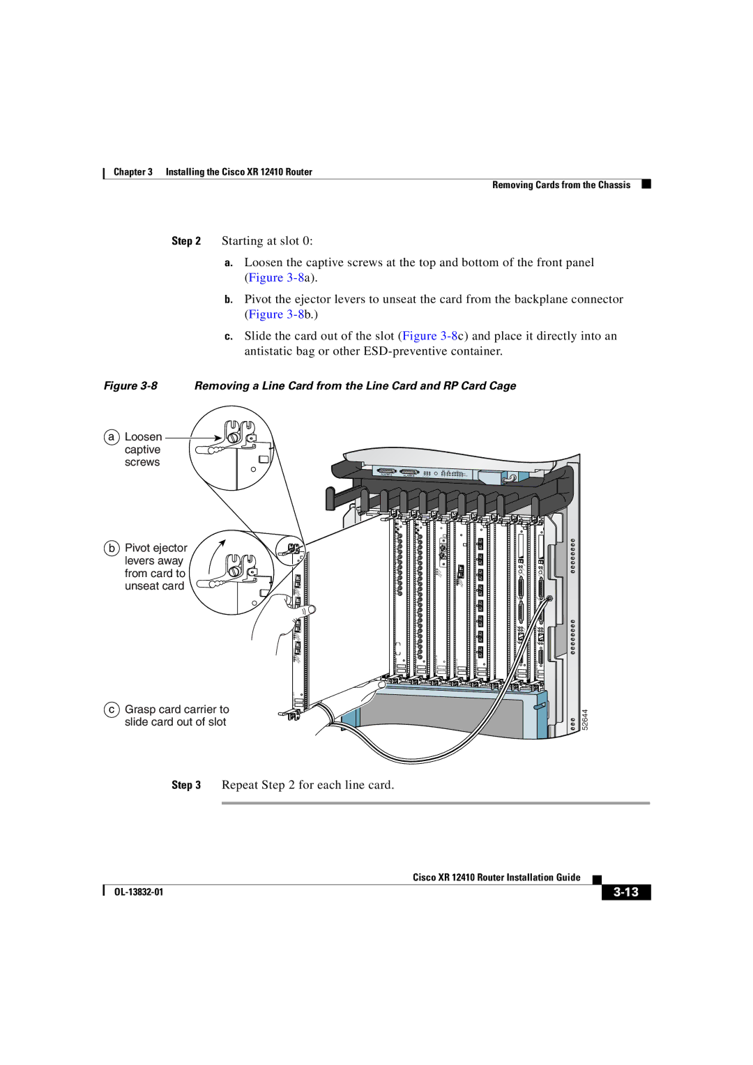
Step 2 Starting at slot 0:
a.Loosen the captive screws at the top and bottom of the front panel (Figure
b.Pivot the ejector levers to unseat the card from the backplane connector (Figure
c.Slide the card out of the slot (Figure
Figure 3-8 Removing a Line Card from the Line Card and RP Card Cage
aLoosen
captive screws
ALARM A | ALARM B |
bPivot ejector
levers away from card to unseat card
cGrasp card carrier to slide card out of slot
0
A
C
T
C IV
A E
R
R R
X IE
P R
K
T
1
A
C
T
C IV
A E
R
R R
X IE
P R
K
T
2
A
C
T
C IV
A E
R
R R
X IE
P R
K
T
3
A
C
T
C IV
A E
R
R R
X IE
P R
K
T
Q OC
ALARM A | ALARM B |
TX | TX |
0 | 0 |
RX | RX |
TX | TX |
1 | 1 |
RX | RX |
TX | TX |
2 | 2 |
RX | RX |
TX | TX |
3 | 3 |
RX | RX |
TX | TX |
4 | 4 |
RX | RX |
TX | TX |
5 | 5 |
RX | RX |
| TX |
| 6 |
| RX |
| TX |
| 7 |
| RX |
| TX |
| 8 |
| RX |
| TX |
| 9 |
| RX |
| TX |
| 10 |
| RX |
| TX |
| 11 |
| RX |
| |
P/H/F | P/H/F |
ACTIVE
AR
RXRIER
PKT
![]()
|
|
| E |
|
|
| JECT |
|
| ||
0 |
|
|
|
|
| A | R |
|
| UX | ESET |
| ACT |
|
|
| CAIVE |
|
|
| RRR |
|
|
| XCIER |
|
|
| ELL |
|
|
|
| C |
|
|
| ONS |
|
|
| OLE |
|
|
| LINK |
|
|
|
| C |
|
| TX | OLL |
|
|
| RX |
|
| M |
|
|
| II | R |
|
|
| |
FAST ETERNET | ROUTE PROCESSOR |
| |
| EJECT |
AUX | RESET |
CON |
|
SOLE |
|
LINK |
|
| C |
TX | OLL |
| RX |
MII |
|
| |
ROUTE PROCESSOR |
|
52644
Step 3 Repeat Step 2 for each line card.
| Cisco XR 12410 Router Installation Guide |
|
|
|
| ||
|
|
|