10 | Installation ~ Hardware Setup |
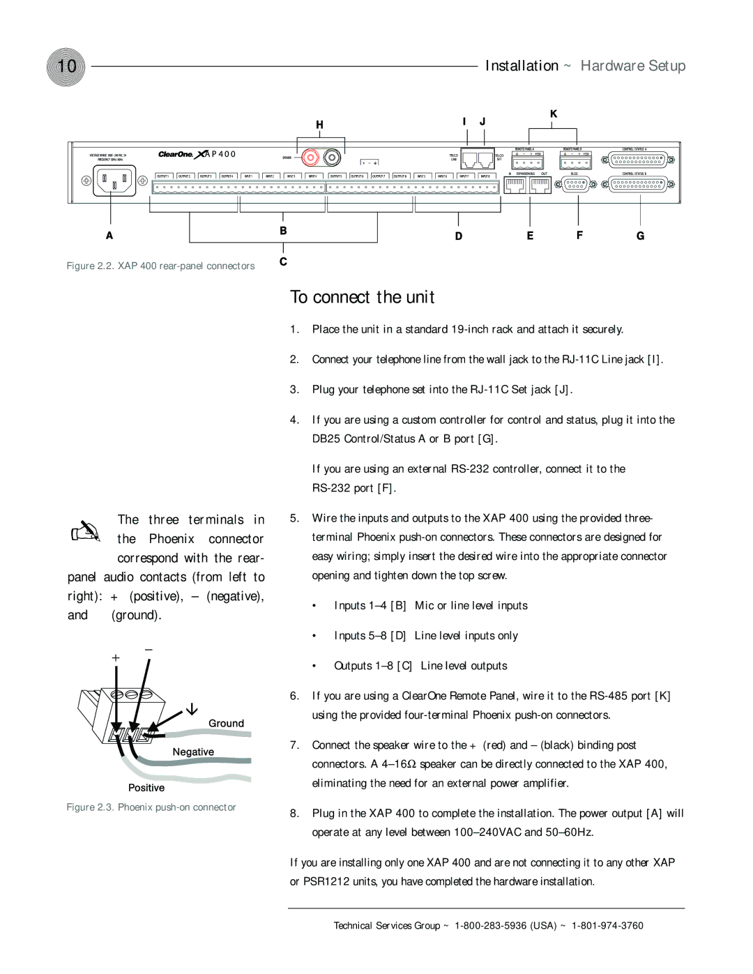
Figure 2.2. XAP 400 rear-panel connectors
The | three | terminals in | |
✍ the | Phoenix | connector | |
correspond | with | the rear- | |
panel audio contacts (from left to right): + (positive), – (negative), and (ground).
Figure 2.3. Phoenix push-on connector
To connect the unit
1.Place the unit in a standard
2.Connect your telephone line from the wall jack to the
3.Plug your telephone set into the
4.If you are using a custom controller for control and status, plug it into the DB25 Control/Status A or B port [G].
If you are using an external
5.Wire the inputs and outputs to the XAP 400 using the provided three- terminal Phoenix
•Inputs
•Inputs
•Outputs
6.If you are using a ClearOne Remote Panel, wire it to the
7.Connect the speaker wire to the + (red) and – (black) binding post connectors. A
8.Plug in the XAP 400 to complete the installation. The power output [A] will operate at any level between
If you are installing only one XAP 400 and are not connecting it to any other XAP or PSR1212 units, you have completed the hardware installation.
Technical Services Group ~