Chapter 2. Getting Started the BHT and System Mode
2.2 Components and Functions
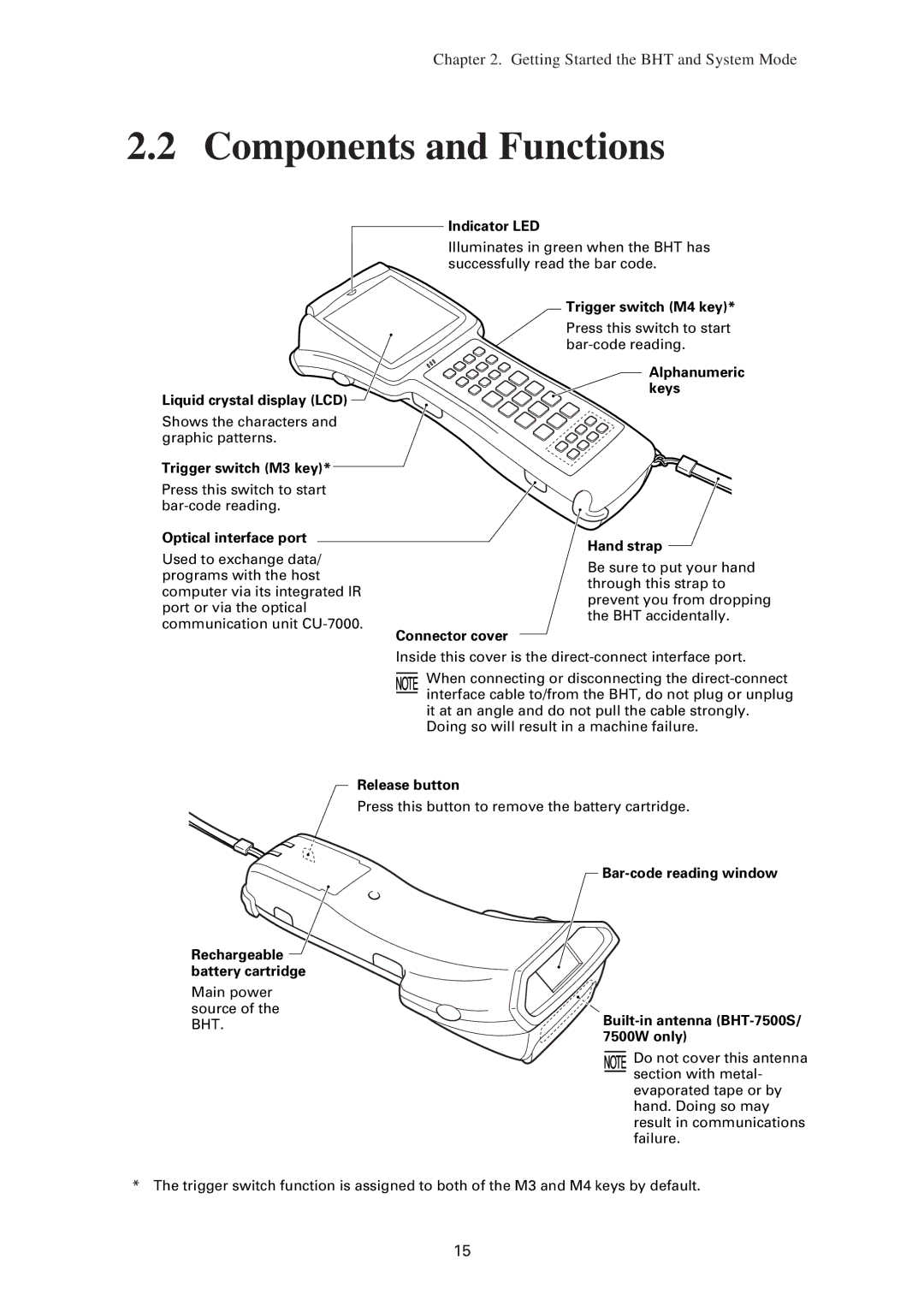
Indicator LED
Illuminates in green when the BHT has successfully read the bar code.
Liquid crystal display (LCD) ![]()
Shows the characters and graphic patterns.
Trigger switch (M3 key)*
Press this switch to start
Optical interface port
Used to exchange data/ programs with the host computer via its integrated IR port or via the optical communication unit
Connector cover
Trigger switch (M4 key)*
Press this switch to start
Alphanumeric keys
Hand strap
Be sure to put your hand through this strap to prevent you from dropping the BHT accidentally.
Rechargeable battery cartridge
Main power source of the BHT.
Inside this cover is the
When connecting or disconnecting the
Doing so will result in a machine failure.
Release button
Press this button to remove the battery cartridge.
Do not cover this antenna section with metal- evaporated tape or by hand. Doing so may result in communications failure.
* The trigger switch function is assigned to both of the M3 and M4 keys by default.
15