6 Message Reference
3E1 120 ohm balanced interface
4T1 (including J1)
5E1 120 ohm balanced interface
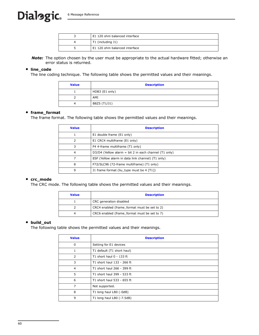
Note: The option chosen by the user must be appropriate to the actual hardware fitted; otherwise an error status is returned.
•line_code
The line coding technique. The following table shows the permitted values and their meanings.
Value | Description |
1HDB3 (E1 only)
2AMI
4 | B8ZS (T1/J1) |
•frame_format
The frame format. The following table shows the permitted values and their meanings.
Value | Description |
|
|
1 | E1 double frame (E1 only) |
|
|
2 | E1 CRC4 multiframe (E1 only) |
|
|
3 | F4 |
|
|
4 | D3/D4 (Yellow alarm = bit 2 in each channel (T1 only) |
|
|
7 | ESF (Yellow alarm in data link channel) (T1 only) |
|
|
8 | F72/SLC96 |
|
|
9 | J1 frame format (liu_type must be 4 [T1]) |
|
|
•crc_mode
The CRC mode. The following table shows the permitted values and their meanings.
Value | Description |
1CRC generation disabled
2CRC4 enabled (frame_format must be set to 2)
4 | CRC6 enabled (frame_format must be set to 7) |
•build_out
The following table shows the permitted values and their meanings.
Value | Description |
|
|
0 | Setting for E1 devices |
|
|
1 | T1 default (T1 short haul) |
|
|
2 | T1 short haul 0 - 133 ft |
|
|
3 | T1 short haul 133 - 266 ft |
|
|
4 | T1 short haul 266 - 399 ft |
|
|
5 | T1 short haul 399 - 533 ft |
|
|
6 | T1 short haul 533 - 655 ft |
|
|
7 | Not supported. |
|
|
8 | T1 long haul LB0 |
|
|
9 | T1 long haul LB0 |
|
|
60