4 Dialogic® DSI SS7MD Board Configuration and Operation
4.8Switching Timeslots between LIUs
The Dialogic DSI SS7MD Boards support multiple T1/E1/J1 Line Interface Units (LIUs). The onboard signaling processor handles the SS7 signaling timeslots, while the remaining circuits (voice or data bearer circuits) are switched to another onboard LIU for distribution to other boards.
Communication between the application and the board is
One of the roles of the application is to control the dynamic switching between LIUs. This section provides details of how to interface with the cross connect switch, including the initial (static) configuration and the subsequent (dynamic) switching. The operation of the switching interface is described in terms of the SCbus switching model using:
•
•
MVD_MSG_SC_DRIVE_LIU and MVD_MSG_SC_LISTEN messages
LIU_SC_DRIVE, SCBUS_LISTEN, and STREAM_XCON config.txt commands
4.8.1Switching Model
The basic switching model assumes that at system initialization all incoming T1/E1/J1 timeslots and all resource board output timeslots are connected to channels on the cross connect switch and that these connections are never changed. This scheme has the advantage that once the cross connect switch drivers have been set up, they are never changed, reducing the chances of inadvertently causing switch conflict. It also means that the user can predict the exact switch channels where any input timeslot can be located, which in turn can assist with fault diagnosis and general system test.
Having completed system initialization, drives to the switch are set up. Then, on a dynamic
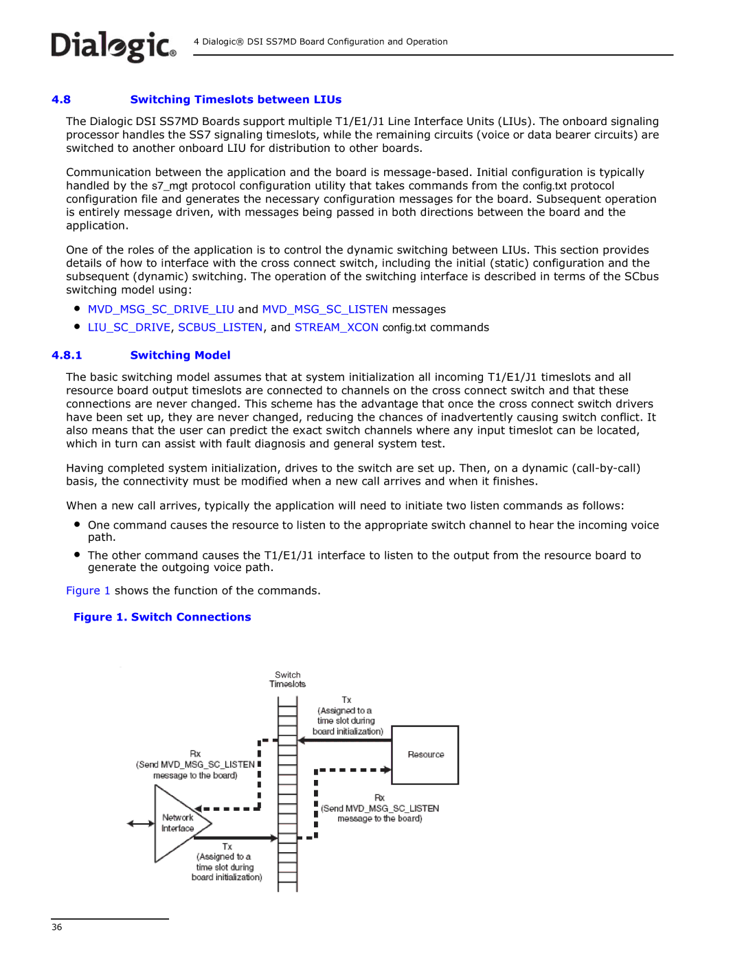
When a new call arrives, typically the application will need to initiate two listen commands as follows:
•One command causes the resource to listen to the appropriate switch channel to hear the incoming voice path.
•The other command causes the T1/E1/J1 interface to listen to the output from the resource board to generate the outgoing voice path.
Figure 1 shows the function of the commands.
Figure 1. Switch Connections
Switch
36