Dialogic® DSI SS7MD Programmer’s Manual Issue 3
Configure the LSL timeslot rate:
•l1_resource_id
Layer 1 (logical) resource identifier.
•data_rate
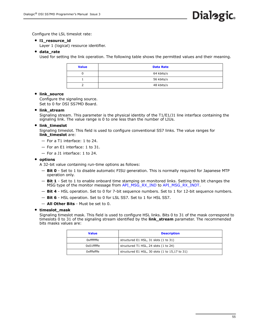
Used for setting the link operation. The following table shows the permitted values and their meaning.
Value
0
1
2
Data Rate
64kbits/s
56kbits/s
48kbits/s
•link_source
Configure the signaling source. Set to 0 for DSI SS7MD Board.
•link_stream
•
•
•
Signaling stream. This parameter is the physical identity of the T1/E1/J1 line interface containing the signaling link. The value range is 0 to one less than the number of LIUs.
link_timeslot
Signaling timeslot. This field is used to configure conventional SS7 links. The value ranges for link_timeslot are:
—For a T1 interface: 1 to 24.
—For an E1 interface: 1 to 31.
—For a J1 interface: 1 to 24.
options
A
—Bit 0 - Set to 1 to disable automatic FISU generation. This is normally required for Japanese MTP operation only.
—Bit 1 - Set to 1 to enable onboard time stamping on monitored links. Setting this bit changes the MSG type of the monitor message from API_MSG_RX_IND to API_MSG_RX_INDT.
—Bit 4 - HSL operation. Set to 0 for
—Bit 6 - HSL operation. Set to 0 for LSL SS7. Set to 1 for HSL SS7.
—All Other Bits - Must be set to 0.
timeslot_mask
Signaling timeslot mask. This field is used to configure HSL links. Bits 0 to 31 of the mask correspond to timeslots 0 to 31 of the signaling stream identified by the link_stream parameter. The recommended bits masks values are:
Value |
| Description |
|
|
|
0xfffffffe | structured E1 | HSL, 31 slots (1 to 31) |
|
| |
0x01fffffe | structured T1 HSL, 24 slots (1 to 24) | |
|
|
|
0xfffefffe | structured E1 | HSL, 30 slots (1 to 15,17 to 31) |
|
|
|
55
