Hardware Configuration
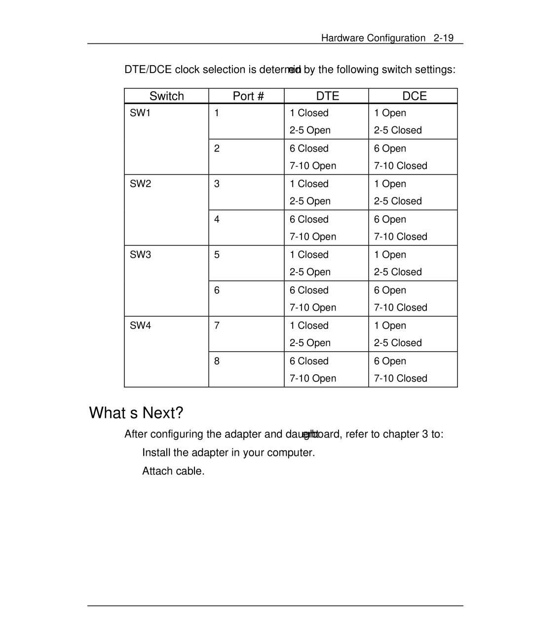
DTE/DCE clock selection is determined by the following switch settings:
Switch | Port # | DTE | DCE |
SW1 | 1 | 1 Closed | 1 Open |
|
| ||
|
|
|
|
| 2 | 6 Closed | 6 Open |
|
| ||
|
|
|
|
SW2 | 3 | 1 Closed | 1 Open |
|
| ||
|
|
|
|
| 4 | 6 Closed | 6 Open |
|
| ||
|
|
|
|
SW3 | 5 | 1 Closed | 1 Open |
|
| ||
|
|
|
|
| 6 | 6 Closed | 6 Open |
|
| ||
|
|
|
|
SW4 | 7 | 1 Closed | 1 Open |
|
| ||
|
|
|
|
| 8 | 6 Closed | 6 Open |
|
| ||
|
|
|
|
What’s Next?
After configuring the adapter and daughterboard, refer to chapter 3 to:
Install the adapter in your computer.
Attach cable.