Hardware Configuration
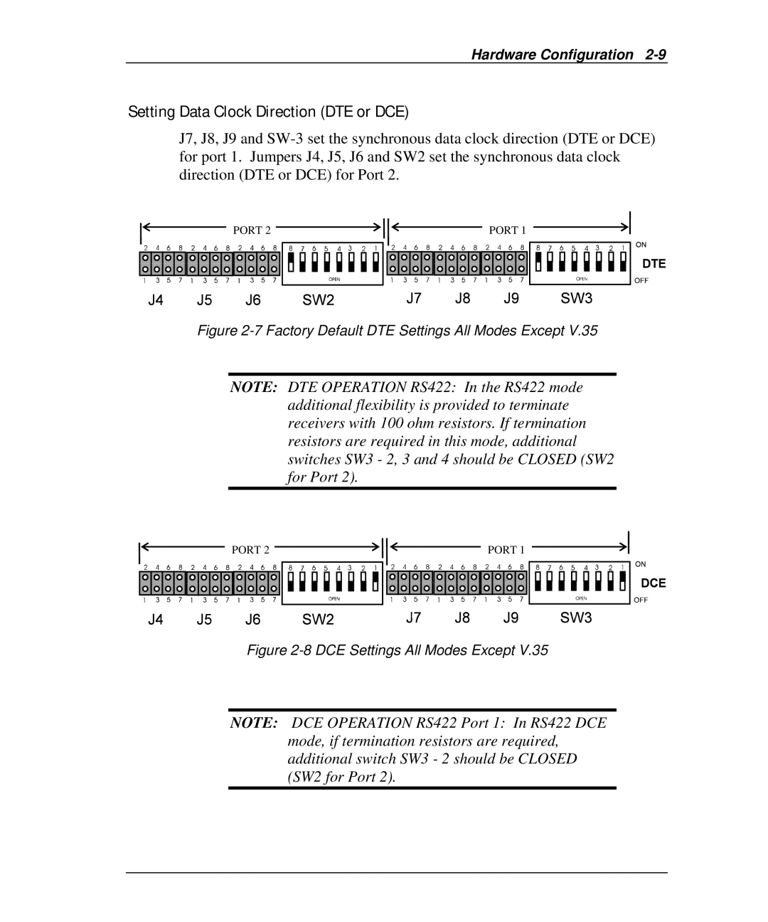
Setting Data Clock Direction (DTE or DCE)
J7, J8, J9 and
![]() PORT 2
PORT 2 ![]()
![]() PORT 1
PORT 1 ![]()
Figure 2-7 Factory Default DTE Settings All Modes Except V.35
NOTE: DTE OPERATION RS422: In the RS422 mode additional flexibility is provided to terminate receivers with 100 ohm resistors. If termination resistors are required in this mode, additional switches SW3 - 2, 3 and 4 should be CLOSED (SW2 for Port 2).
![]() PORT 2
PORT 2 ![]()
![]() PORT 1
PORT 1 ![]()
Figure 2-8 DCE Settings All Modes Except V.35
NOTE: DCE OPERATION RS422 Port 1: In RS422 DCE mode, if termination resistors are required, additional switch SW3 - 2 should be CLOSED (SW2 for Port 2).