Uninstall using NetWare version 4.1
1) At the console server prompt, type:
>LOAD INETCFG <Enter>.
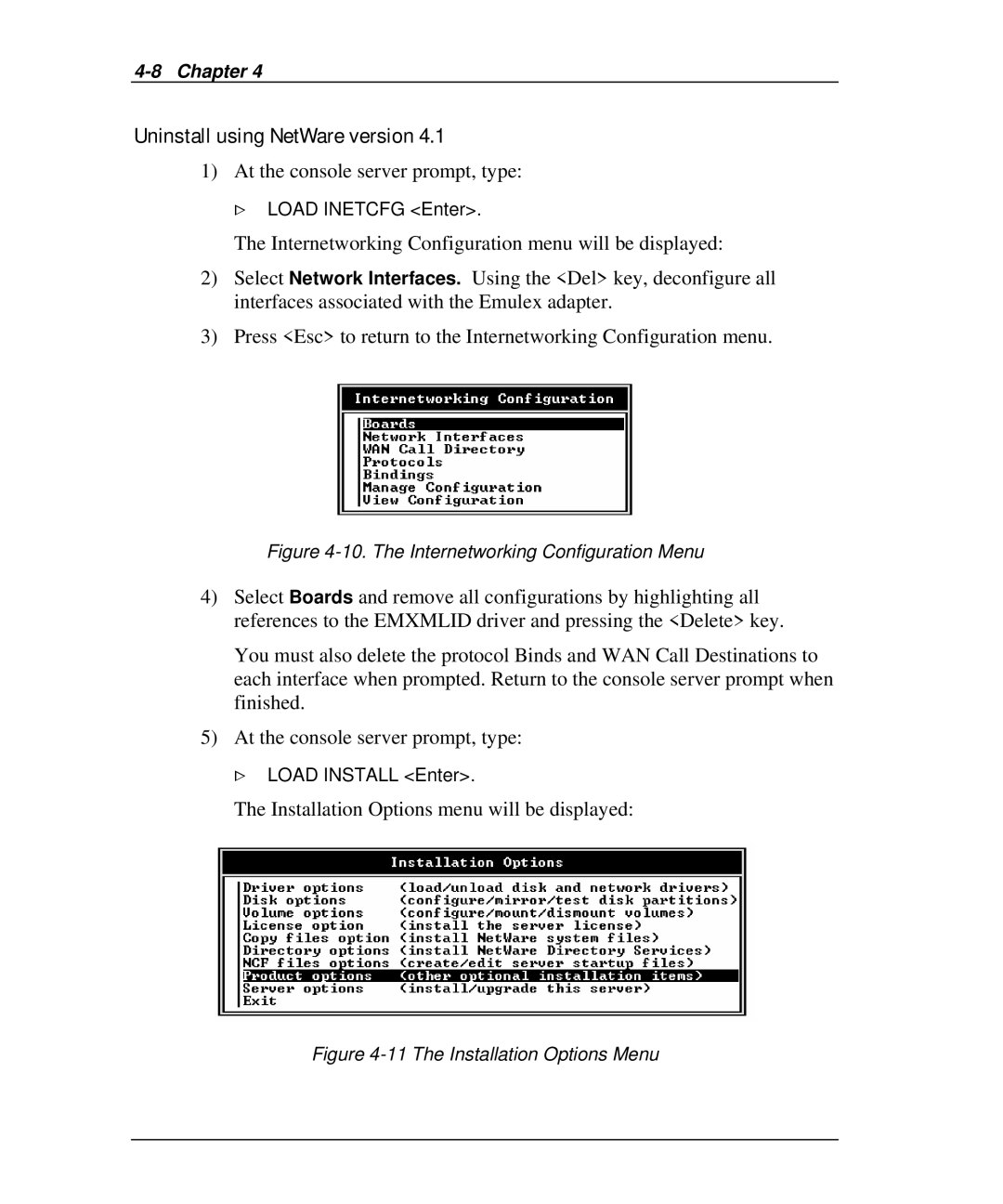
The Internetworking Configuration menu will be displayed:
2)Select Network Interfaces. Using the <Del> key, deconfigure all interfaces associated with the Emulex adapter.
3)Press <Esc> to return to the Internetworking Configuration menu.
Figure 4-10. The Internetworking Configuration Menu
4)Select Boards and remove all configurations by highlighting all references to the EMXMLID driver and pressing the <Delete> key.
You must also delete the protocol Binds and WAN Call Destinations to each interface when prompted. Return to the console server prompt when finished.
5)At the console server prompt, type:
>LOAD INSTALL <Enter>.