|
| Specifications | ||
|
| Electrical Measurements23 | ||
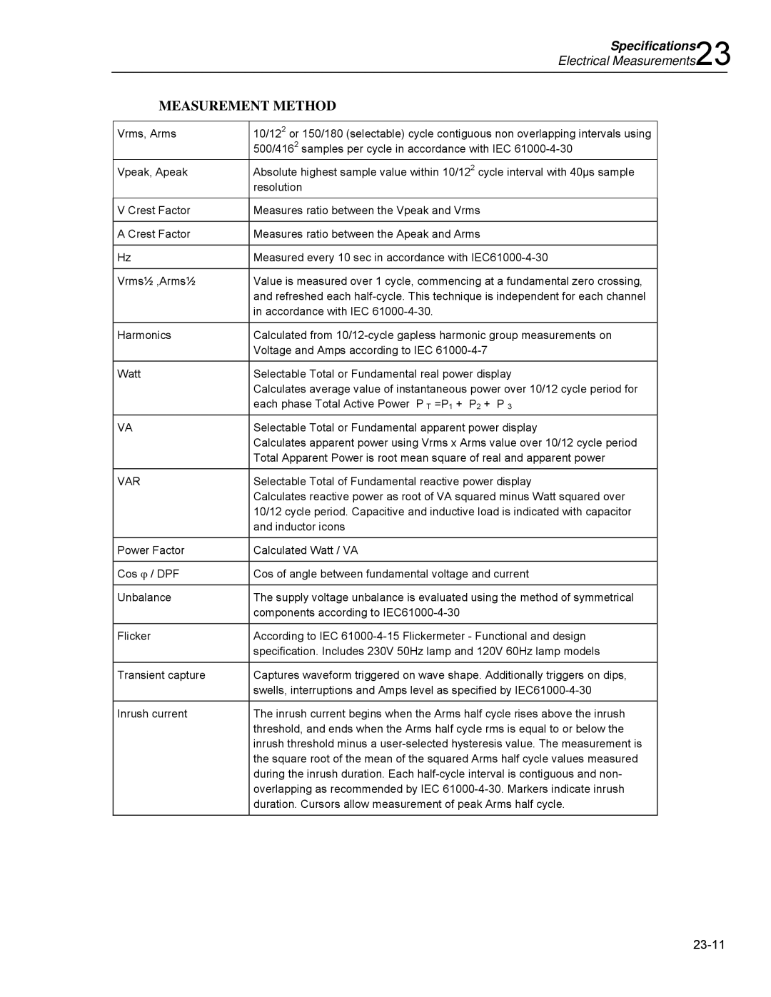
| MEASUREMENT METHOD |
| ||
|
|
|
| |
| Vrms, Arms | 10/122 or 150/180 (selectable) cycle contiguous non overlapping intervals using |
| |
|
| 500/4162 samples per cycle in accordance with IEC |
| |
| Vpeak, Apeak | Absolute highest sample value within 10/122 cycle interval with 40µs sample |
| |
|
| resolution |
| |
|
|
|
| |
| V Crest Factor | Measures ratio between the Vpeak and Vrms |
| |
|
|
|
| |
| A Crest Factor | Measures ratio between the Apeak and Arms |
| |
|
|
|
| |
| Hz | Measured every 10 sec in accordance with |
| |
|
|
|
| |
| Vrms½ ,Arms½ | Value is measured over 1 cycle, commencing at a fundamental zero crossing, |
| |
|
| and refreshed each |
| |
|
| in accordance with IEC |
| |
|
|
|
| |
| Harmonics | Calculated from |
| |
|
| Voltage and Amps according to IEC |
| |
|
|
|
| |
| Watt | Selectable Total or Fundamental real power display |
| |
|
| Calculates average value of instantaneous power over 10/12 cycle period for |
| |
|
| each phase Total Active Power P T =P1 + P2 + P 3 |
| |
|
|
|
| |
| VA | Selectable Total or Fundamental apparent power display |
| |
|
| Calculates apparent power using Vrms x Arms value over 10/12 cycle period |
| |
|
| Total Apparent Power is root mean square of real and apparent power |
| |
|
|
|
| |
| VAR | Selectable Total of Fundamental reactive power display |
| |
|
| Calculates reactive power as root of VA squared minus Watt squared over |
| |
|
| 10/12 cycle period. Capacitive and inductive load is indicated with capacitor |
| |
|
| and inductor icons |
| |
|
|
|
| |
| Power Factor | Calculated Watt / VA |
| |
|
|
|
| |
| Cos ϕ / DPF | Cos of angle between fundamental voltage and current |
| |
|
|
|
| |
| Unbalance | The supply voltage unbalance is evaluated using the method of symmetrical |
| |
|
| components according to |
| |
|
|
|
| |
| Flicker | According to IEC |
| |
|
| specification. Includes 230V 50Hz lamp and 120V 60Hz lamp models |
| |
|
|
|
| |
| Transient capture | Captures waveform triggered on wave shape. Additionally triggers on dips, |
| |
|
| swells, interruptions and Amps level as specified by |
| |
|
|
|
| |
| Inrush current | The inrush current begins when the Arms half cycle rises above the inrush |
| |
|
| threshold, and ends when the Arms half cycle rms is equal to or below the |
| |
|
| inrush threshold minus a |
| |
|
| the square root of the mean of the squared Arms half cycle values measured |
| |
|
| during the inrush duration. Each |
| |
|
| overlapping as recommended by IEC |
| |
|
| duration. Cursors allow measurement of peak Arms half cycle. |
| |
|
|
|
|
|
Page 131
Image 131