Fluke 434/435
Users Manual
Figure 6-1. Mounting the decals for voltage and current inputs
For a
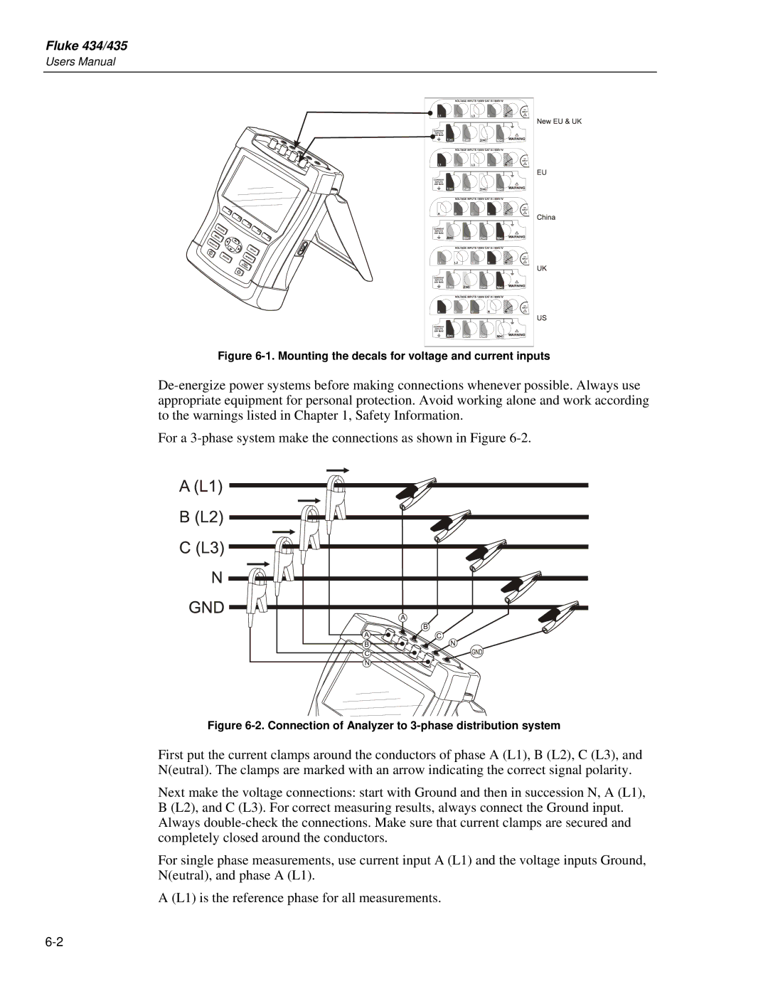
Figure 6-2. Connection of Analyzer to 3-phase distribution system
First put the current clamps around the conductors of phase A (L1), B (L2), C (L3), and N(eutral). The clamps are marked with an arrow indicating the correct signal polarity.
Next make the voltage connections: start with Ground and then in succession N, A (L1), B (L2), and C (L3). For correct measuring results, always connect the Ground input. Always
For single phase measurements, use current input A (L1) and the voltage inputs Ground, N(eutral), and phase A (L1).
A (L1) is the reference phase for all measurements.