Fluke 434/435
Users Manual
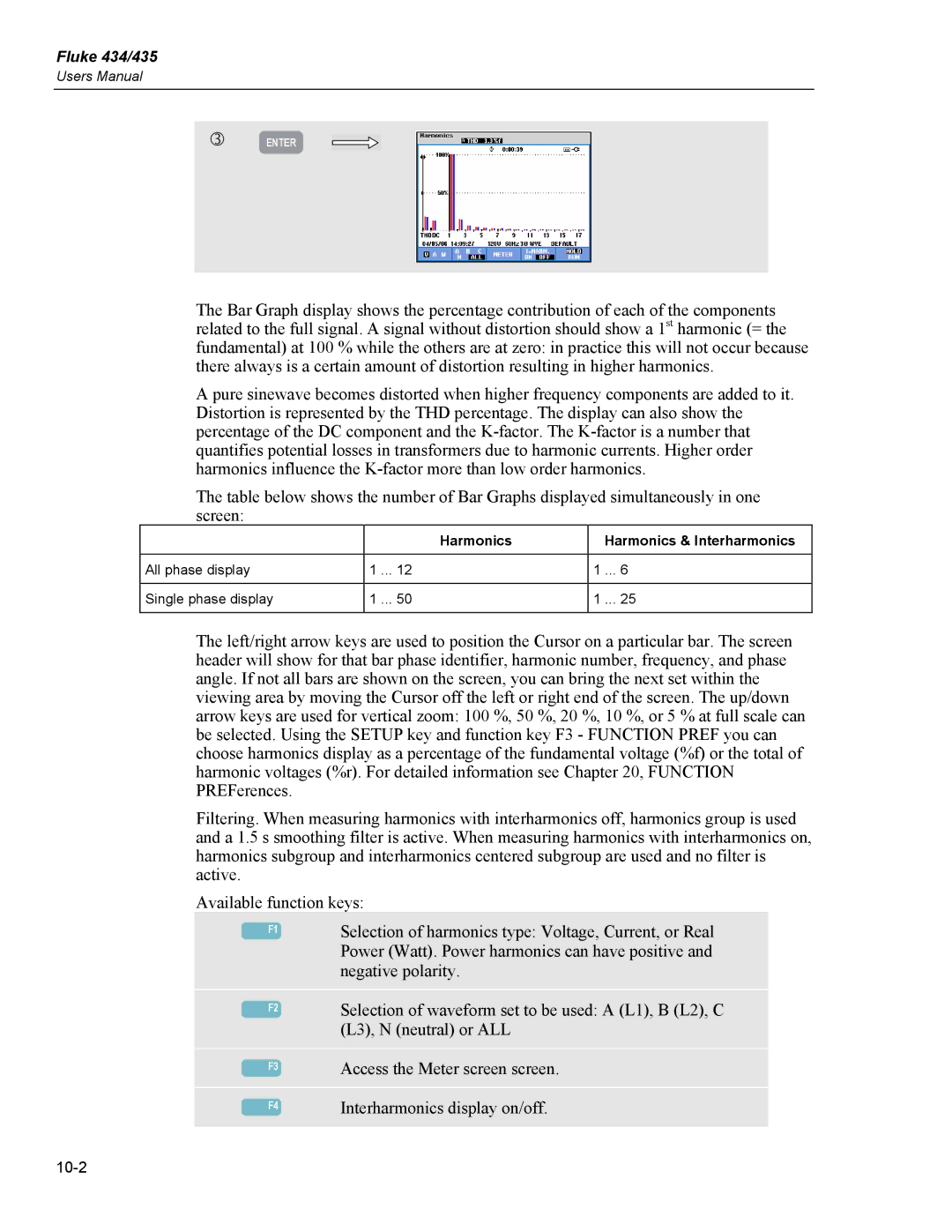
e | ENTER |
The Bar Graph display shows the percentage contribution of each of the components related to the full signal. A signal without distortion should show a 1st harmonic (= the fundamental) at 100 % while the others are at zero: in practice this will not occur because there always is a certain amount of distortion resulting in higher harmonics.
A pure sinewave becomes distorted when higher frequency components are added to it. Distortion is represented by the THD percentage. The display can also show the percentage of the DC component and the
The table below shows the number of Bar Graphs displayed simultaneously in one screen:
|
| Harmonics |
| Harmonics & Interharmonics |
|
|
|
|
|
All phase display | 1 ... | 12 | 1 | ... 6 |
|
|
|
|
|
Single phase display | 1 ... | 50 | 1 | ... 25 |
|
|
|
|
|
The left/right arrow keys are used to position the Cursor on a particular bar. The screen header will show for that bar phase identifier, harmonic number, frequency, and phase angle. If not all bars are shown on the screen, you can bring the next set within the viewing area by moving the Cursor off the left or right end of the screen. The up/down arrow keys are used for vertical zoom: 100 %, 50 %, 20 %, 10 %, or 5 % at full scale can be selected. Using the SETUP key and function key F3 - FUNCTION PREF you can choose harmonics display as a percentage of the fundamental voltage (%f) or the total of harmonic voltages (%r). For detailed information see Chapter 20, FUNCTION PREFerences.
Filtering. When measuring harmonics with interharmonics off, harmonics group is used and a 1.5 s smoothing filter is active. When measuring harmonics with interharmonics on, harmonics subgroup and interharmonics centered subgroup are used and no filter is active.
Available function keys:
|
|
|
|
| Selection of harmonics type: Voltage, Current, or Real |
| F1 |
| |||
|
|
|
|
| Power (Watt). Power harmonics can have positive and |
|
|
|
|
| negative polarity. |
|
|
|
|
|
|
|
|
|
|
| Selection of waveform set to be used: A (L1), B (L2), C |
| F2 |
| |||
|
|
|
|
| (L3), N (neutral) or ALL |
|
|
|
|
|
|
|
|
|
|
| Access the Meter screen screen. |
| F3 |
|
| ||
|
|
|
|
|
|
|
|
|
|
| Interharmonics display on/off. |
| F4 |
|
| ||
|
|
|
|
|
|