Chapter 7
Scope Waveform and Phasor
Introduction
Scope mode shows voltages and currents in the power system under test by means of waveforms or vector diagram. Also numerical values are shown such as phase voltages, phase currents, frequency, and phase angles between voltages and currents.
Scope Waveform
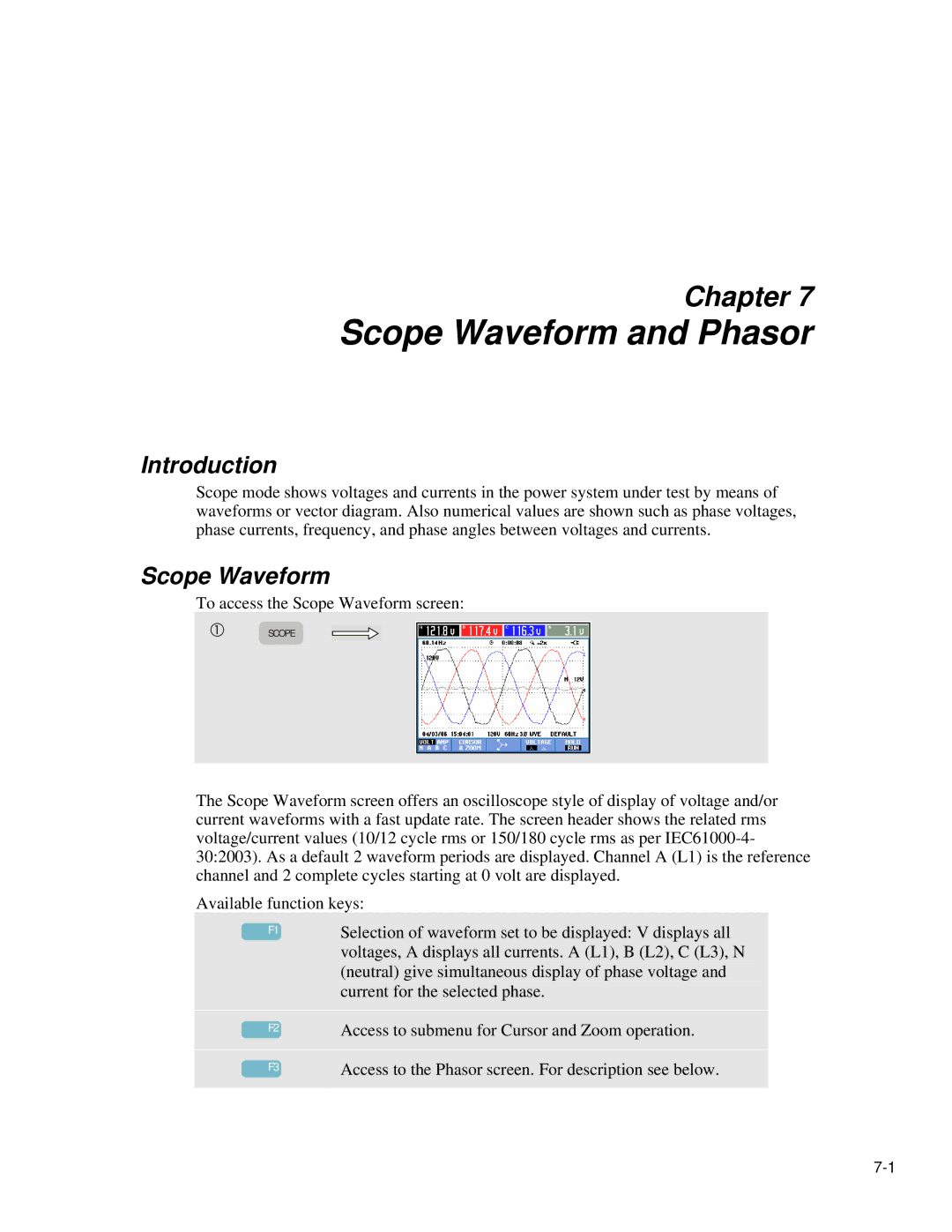
To access the Scope Waveform screen:
c | SCOPE |
The Scope Waveform screen offers an oscilloscope style of display of voltage and/or current waveforms with a fast update rate. The screen header shows the related rms voltage/current values (10/12 cycle rms or 150/180 cycle rms as per
Available function keys:
|
|
| Selection of waveform set to be displayed: V displays all |
| F1 | ||
|
|
| voltages, A displays all currents. A (L1), B (L2), C (L3), N |
|
|
|
(neutral) give simultaneous display of phase voltage and current for the selected phase.
F2
F3
Access to submenu for Cursor and Zoom operation.
Access to the Phasor screen. For description see below.