DTC400/DTC300/DTC300M Card Printer User Guide Rev
Part Number
Revision Control Date Document Title Number
Table of Contents
General Troubleshooting
Restricted USE ONLYFargo Electronics, Inc
Parts Replacement Packing the Card Printer
Reviewing the Spare Parts List
How to use the manual
Manual Description
To prevent equipment or media damage, always wear an
Safety Messages review carefully
Exposed to static electricity discharges
To prevent equipment or media damage, always remove
Reviewing the DTC400/DTC300/DTC300M Block Diagram
DTC400/DTC300/DTC300M Card Printer Overview
Reviewing the DTC400/DTC300/DTC300M Sequence of Operations
Step Process
Reviewing the DTC400/DTC300/DTC300M Sequence of Operations
All Stop
Encoding data is written to the card
Card is ejected from the Printer
Reviewing the DTC400/DTC300/DTC300M Boot up Sequence
Specifications
File Number E145118
Regulatory Compliances
Term Description
License Number
Type Description
Technical Specifications
Agency Listings
Technical Specifications
DTC400/DTC300/DTC300M CR-80edge-to-edge
Technical Specifications
Custom HoloMarkTM Cards
Visual Security Solutions Specifications
VeriMarkTM Cards 2-D holographic foil application
Visual Security Card Stock Part Numbers
VeriMarkTM Application Specifications
HoloMarkTM and Custom HoloMarkTM Application Specifications
Panels on the Ribbon
Functional Specifications
Function Description
Components Description
Cancel button
Printer Components Front Cover
Pause button
Printer Components Print Ribbons
Printer Components Resin-Only Print Ribbons
Step Procedure
Printer Components Dye-Sublimation Print Ribbons
Printer Components Dye-Sublimation/Resin Print Ribbons
Printer Components Blank Cards
Setup and Installation Procedures
Restricted USE ONLYFargo Electronics, Inc
About Moisture Condensation
Printer Setup and Installation
Choosing a Good Location
Unpacking and Inspection
Restricted USE only
Reviewing the LCD top-front part of Printer
Connecting the Printer power
Installing the Print Ribbon Cartridge
Installing the Print Ribbon Cartridge
Installing the Print Ribbon Cartridge
Installing Blank Cards into the Card Hopper
Step
Installing Blank Cards into the Card Hopper
Installing Blank Cards into the Card Hopper
Lowering the Card Output Hopper
Printer Driver Installation
Installing the Printer Driver
Installing the Printer Driver
Step Procedure Wait during the installation
Click on the Next button to continue with the Setup program
Installing the Printer Driver
Printer Driver Software
Fargo Diagnostics Utility
Install
Printer Driver User’s Guide
Click Install to begin the installation
Installing the Printer Driver
Connect the USB cable to the Printer
Turn on the Printer at this time if it is not already on
Wait while the Driver components are being copied to your PC
Installing the Printer Driver
Installing the Printer Driver
Step Procedure You have completed the installation
Printing a Test Print Image
Printing a Test Print Image
Printer Transport
Moving the Printer to another location
General Troubleshooting
Restricted USE ONLYFargo Electronics, Inc
Safety Messages review carefully
Communications Errors
Resolving the Communication Errors
Resolving the Communication Errors
Print Process Errors
Check the card quality / loading
Reboot the Printer by cycling the power
Using the Diagnostic Utility tabs
Remove cards from the Card Hopper
Step Procedure
Step
Check Card Feed TOF Sensor
Clean the Card Feed Roller
Check card quality / loading
Remove the Printers rear cover
Step
Step Procedure
Review the following information
LCD Error Display Ribbon Rfid Error
If the error continues, replace the Printer Main Board
Ribbon
Resolving the Mag Verify Error
Resolving a Mag Verify Error
Resolving a Mag Verify Error
Resolving the No Mag Installed Error
Resolving a No Mag Installed Error
Resolving a Ribbon Sensor Error Ribbon Miscue
Resolving a Ribbon Sensor Error Ribbon Miscue
Resolving a Ribbon Break Jam Error
Resolving a Ribbon Break Jam Error
LCD Error Display Ribbon Out
Resolving a Ribbon Out Error
Symptom Printer will not print
Driver Monitor Error Display Ribbon Out
Resolving a No Ribbon Installed Error
Resolving a No Ribbon Installed Error
Resolving a Invalid Ribbon Error
Resolving a Invalid Ribbon Error
Model
Resolving a Wrong Ribbon Error
Resolving a Wrong Ribbon Error
Resolving a Card Jam Error
Resolving a Card Jam Error
Resolving a Headlift Motor or Sensor Error
Resolving a Headlift Motor or Sensor Error
Driver Monitor Error Display None
Resolving the Cover Open Error Message
LCD Error Display Cover Open
LCD Error Display None
Resolving the Blank Output issues
Printer Error State None
Resolving the Blank Output issues
Preferences
Resolving the Blank Output issues
Assembly D900023
Diagnosing Image Problems
Resolving the Pixel Failure problems
Sample image below
Cards with embedded contaminants in the surface
Resolving the Card Surface Debris problems
See sample image below
Resolving the Incorrect Image Darkness problems
Resolving the Incorrect Image Darkness problems
Resolving Ribbon Wrinkle problems
Resolving Ribbon Wrinkle problems
Resolving the Excessive Resin Printing problems
Resolving the Excessive Resin Printing problems
Resolving the Incomplete Resin Printing problems
Appears
Resolving the Image Placement problems
Where the white border is on the card
Incorrectly
Resolving the Image Placement problems
Graphic a
Resolving the Image Placement problems
Resolving the Poor Image Quality problems
Running the Self Test
Display B Resin Test Print Insert image of resin test print
Running the Standard Self Test Print
Display a Full Color Test Print
Running the Magnetic Self Test HiCo Only
Printer Adjustments
See this section for printer adjustments
Restricted USE ONLYFargo Electronics, Inc
Restricted USE ONLYFargo Electronics, Inc
Safety Messages review carefully
Reviewing DTC400 Printer Drivers
DTC400/DTC300 Print Driver Options
Reviewing DTC400, DTC300 and DTC300M Printer Drivers
This section applies to the DTC400 Printer
Reviewing DTC300 Printer Driver
This section applies to the DTC300 Printer
Reviewing DTC300M Printer Drivers
This section applies to the DTC300M Printer
Using the Card tab
Adjusting the Card Size Option
Adjusting the Orientation Option
Selecting the number of copies
Using the Diagnostics button under the Card tab
Step Description
Using the Clean Printer Option
Place the Cleaning card into the Single Feed Slot
Using the Clean Printer Option
Using the Test Print button
Using the About button
Using the Device Options tab DTC400/DTC300
Adjusting the Ribbon Type option
Selecting the Auto Ribbon Select option
Adjusting the Color Matching option
Adjusting for the Resin Dither
Using the Rotate Image 180 Degrees option
Using the Disable Printing option
Using the Device Options tab DTC300M
Selecting the Auto Ribbon Select option
Adjusting for the Resin Dither
Using the Rotate Image 180 Degrees option
Using the Disable Printing option
Using the Resin Heat K option
Using the Overlay Heat O option
Using the Image Color tab DTC400/DTC300
Using the Resin Heat K option
Using the Overlay Heat O option
Using the Color Matching option and Default button
Using the Calibrate tab
Using the Image Position Controls
Using Image Position controls
Using the Sensors button
Using the Settings button
Using the Magnetic Encoding tab
Using the Magnetic Track Selection radio buttons
Using the Magnetic Track Selection radio buttons
Using the Magnetic Track Options radio buttons
Using the Bit Density radio buttons
Using the Character Size radio buttons
Reviewing the Enable MLE Support checkbox
Using the Ascii Offset radio buttons
Using the LRC Generation radio buttons
Using the Character Parity radio buttons
Using the Shift Data Left checkbox
Reviewing the ISO Track Locations
223 0.353 TRACK1 130 TRACK2 140 TRACK3
Sending the Track Information
Entering the Track Information
Ascii See the table below
Reviewing Tracks 1, 2 and 3 in table format
Reviewing the Track Data Note
Ascii 106 See the table below
Reviewing the Ascii Code and Character Table
Using the Overlay / Print Area tab
Using the Overlay / Print Area dropdown menu
Using the Overlay / Print Area dropdown menu
Using the Overlay / Print Area
Using the Overlay / Print Area
Using the Defined Area Option
Using the Defined Area Option
Karen Atkins
Using the Defined Area Option
Access Level-2 ID#
=1.3 Y=0.3
Using the Defined Area Option
Using Security Options Visual Security Solutions
Selecting Orientation Landscape under Card tab
Selecting the Visual Security Solutions dropdown menu a to D
Selecting Orientation Portrait under Card tab
Selecting the Visual Security Solutions dropdown menu E to H
Selecting the VeriMark radio button
Selecting the HoloMark radio button
Restricted USE only
Restricted USE only
Using the K Panel Resin tab
Selecting from the Print All Black With K Panel options
Selecting the Full Card option
Selecting the Defined Areas option
Selecting the Undefined Areas option
Selecting the Defined Areas function
To define an area, refer to the following steps
172355
Selecting the Defined Areas function
Selecting the Defined Areas function
Refer to the previous procedure
172355
Selecting the Defined Areas function
Step Procedure
Selecting the Print YMC under K and Print K Only options
Using the Printer Supplies tab
Reviewing the Ribbon Information
Reviewing the Ribbon Level Indicator
Using the Printer Calibration Utility
Using the Image Darkness Option
Using the Print Top of Form Option
Using the Print End of Form Option
Rear of Printer
Using the Print Left of Form Option
Using the Magnetic Encoder Voltage Offset Option
Adjusting the Hi-Co Voltage Offset
For example
36500/1.5+4.6/1.23-1-2670/39.0625 126X-1 =
Adjusting the Lo-Co Voltage Offset
Required Encoder Voltage = 1.5vdc
Change the Mag Lo-Co Voltage Offset value
Using the Mag Top of Form Option
Using the Mag Top of Form Option
Use this option to adjust the contrast of the LCD
Using the Ribbon Tension Option
Using the LCD Contrast Option
Cleaning
Safety Messages review carefully
Using the Required Supplies
Cleaning Procedures
Cleaning the Printhead
Cleaning the Card Feed and Cleaning Rollers
Cleaning the Printers Exterior
Cleaning the Printers Interior
Parts Replacement
Wipe it down with a lint-free cloth
Clean the inside of the Printer with compressed air
Clean the Printhead with a alcohol swab
Ensure to enclose any necessary paperwork, test cards, etc
Board Level Diagnostics
Safety Messages review carefully
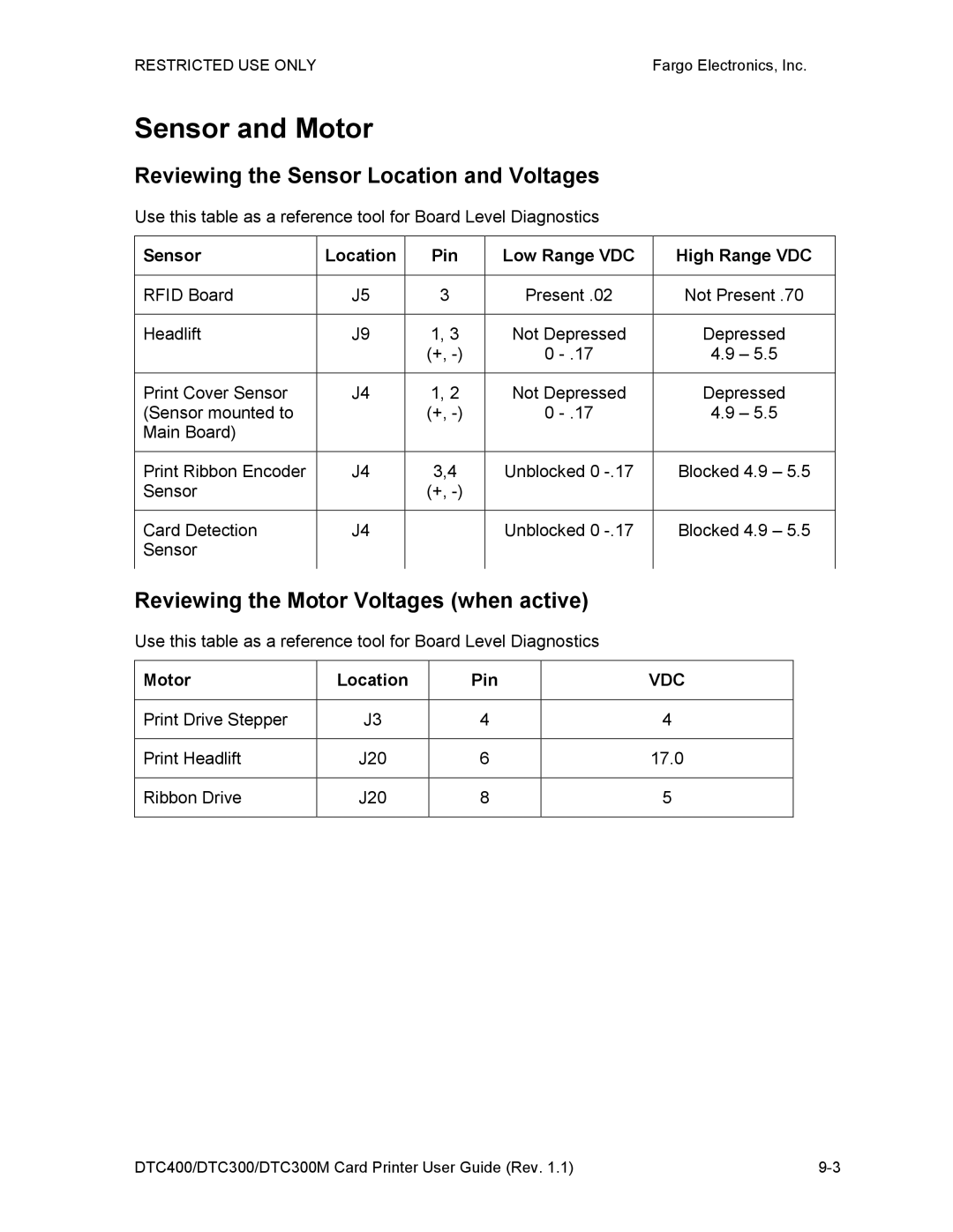
Reviewing the Sensor Location and Voltages
Reviewing the Motor Voltages when active
Sensor and Motor
Sensor Location Pin Low Range VDC High Range VDC
Diagnostic Tool Utility
Using the Diagnostic Tool Utility
Selecting from the Printer Selection menu
DTC400/DTC300/DTC300M Card Printer User Guide Rev 10-3
Step Procedure Select the Print Spooler tab, as shown below
Using the Diagnostic Utility tabs
Selecting the Print Spooler tab in the Diagnostics Utility
Selecting the Print Spooler tab in the Diagnostics Utility
Shown below
Select the Print File .PRN that is to be sent to the Printer
DTC400/DTC300/DTC300M Card Printer User Guide Rev 10-7
DTC400/DTC300/DTC300M Card Printer User Guide Rev 10-8
DTC400/DTC300/DTC300M Card Printer User Guide Rev 10-9
Downloading Firmware Updates
Selecting the Firmware File
Upgrade Firmware
Placing the Printer in the Upgrade Mode
Disconnect Power from the Printer
Press the Yes button on the LCD to continue
Click on the Send Firmware button
Sending the Firmware File
Ensure that the firmware File is selected
Selecting the Mechanics tab in the Diagnostics Utility
Selecting the Mechanics tab in the Diagnostics Utility
Running the Magnetic Self Test HiCo Only procedure on
Cycle up and down
Forward in the Printer
Backwards in the Printer
Printer before selecting this option
DTC400/DTC300/DTC300M Card Printer User Guide Rev 10-20
DTC400/DTC300/DTC300M Card Printer User Guide Rev 10-21
DTC400/DTC300/DTC300M Card Printer User Guide Rev 10-22
DTC400/DTC300/DTC300M Card Printer User Guide Rev 10-23
Selecting the Self Tests tab in the Diagnostics Utility
Use these options to run the internal Printer Self Tests
Selecting the Card Samples tab in the Diagnostics Utility
DTC400/DTC300/DTC300M Card Printer User Guide Rev 10-26
Selecting the Help button in the Diagnostics Utility
Selecting the About button in the Diagnostics Utility
Selecting the Exit button in the Diagnostics Utility
Firmware Upgrades
See Firmware Updates in Diagnostic Tool Utility
Fargo Technical Support
Contacting Fargo Technical Support
Reviewing Example No Serial Number
Finding out when a Fargo Card Printer was manufactured
Reading the Serial Numbers on a Fargo Printer
Reviewing Example No Serial Number A1280224
Reviewing the Spare Parts List
Reviewing the DTC400/DTC300/DTC300M Spare Parts List
Glossary of Terms
Term Definition
Glossary of Terms
DTC400/DTC300/DTC300M Card Printer User Guide Rev 14-3
DTC400/DTC300/DTC300M Card Printer User Guide Rev 14-4
DTC400/DTC300/DTC300M Card Printer User Guide Rev 14-5
Eeprom
Eprom
DTC400/DTC300/DTC300M Card Printer User Guide Rev 14-8
DTC400/DTC300/DTC300M Card Printer User Guide Rev 14-9
ISO
DTC400/DTC300/DTC300M Card Printer User Guide Rev 14-11
DTC400/DTC300/DTC300M Card Printer User Guide Rev 14-12
DTC400/DTC300/DTC300M Card Printer User Guide Rev 14-13
PET
PVC
RGB
DTC400/DTC300/DTC300M Card Printer User Guide Rev 14-17
TAC
DTC400/DTC300/DTC300M Card Printer User Guide Rev 14-19
Black K
Designation of colored Ribbon by the panels of color
Order in which they are printed Yellow Y, Magenta M, Cyan
Black K, Heat Seal H
Index
Restricted USE only
For Print and Overlay
Omit Signature Area setting, 5-58On LED, 4-51,4-53
Print YMC Under K option, 5-83 printable area
Yellow, Magenta and Cyan, 5-29 YMC
Ymcko Ymckok